Method and System for the Treatment of Spinal Deformities

a spinal deformity and spinal nerve technology, applied in the field of spinal nerve deformity treatment, can solve the problems of pain, inability to maintain the functional integrity of the neural elements contained within the spine, and three-dimensional deformity problems

Active Publication Date: 2013-12-05
PEREIRO DE LAMO JAVIER +1
View PDF6 Cites 37 Cited by
  • Summary
  • Abstract
  • Description
  • Claims
  • Application Information

AI Technical Summary

Problems solved by technology

In many cases the loss of the normal aspect and balance of the spine is concomitant with the deterioration of its mechanical integrity which may lead to a diminished pulmonary function, pain and in severe cases to the inability to maintain the functional integrity of the neural elements contained within the spine such as the spine cord and the spinal nerves.
All the deformities of the spinal column, even the most subtle deformities are a three-dimensional deformity problem, as the displacement of the vertebral elements over one axis of the space is almost invariably accompanied by the displacement of the same vertebral elements in the other two axis of the space.
However, the use of distraction and compression forces in these earlier spine instrumentations led in many cases to an abnormal straightening of the physiological “S” shape sagittal balance of the spine, which was in itself a cause of discomfort, pain and functional impairment.
Present surgical spine fixation systems make use of two longitudinal spinal fixing elements (commonly rods) for the definitive fixation of the spine, placing them on each side of the vertebral column, as it has been observed that fixation of the spine with only one longitudinal spinal fixing element leads to material fatigue and failure with worse clinical results.
These surgical spine instrumentations have the disadvantage of distributing the forces employed for the correction of the spine through only half of the vertebral fixation elements that will be finally includ

Method used


Image

  • Method and System for the Treatment of Spinal Deformities
  • Method and System for the Treatment of Spinal Deformities
  • Method and System for the Treatment of Spinal Deformities

Examples


Embodiment Construction

[0065]Disclosed herein are requisite tools and methods for an accurate and preplanned three-dimensional correction of the vertebrae in a deformed spine of a patient. Also provided is a means for the definitive fixation of the spine.

[0066]Vertebral Fixing Elements

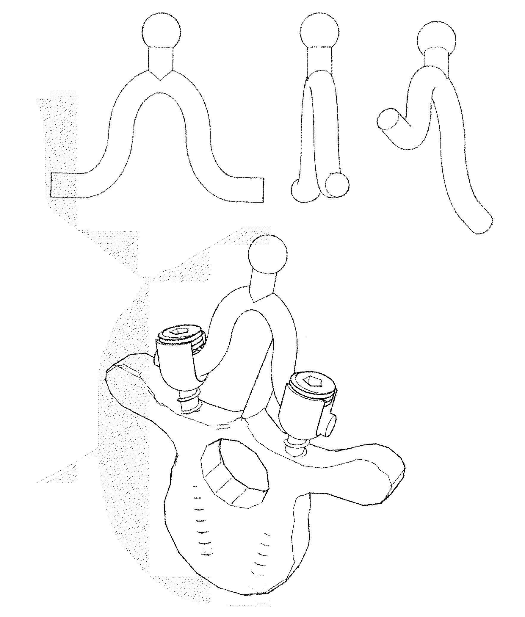
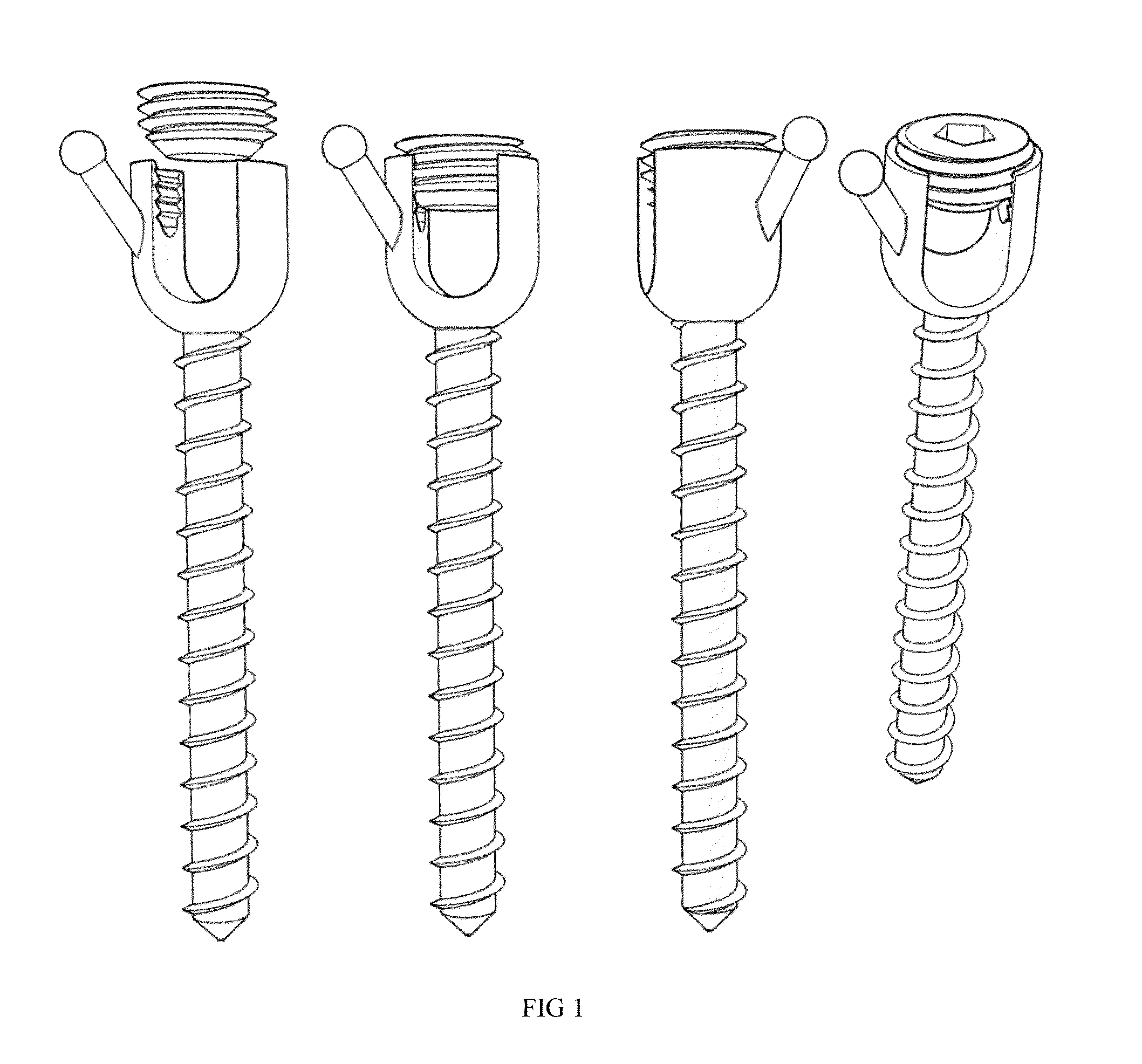
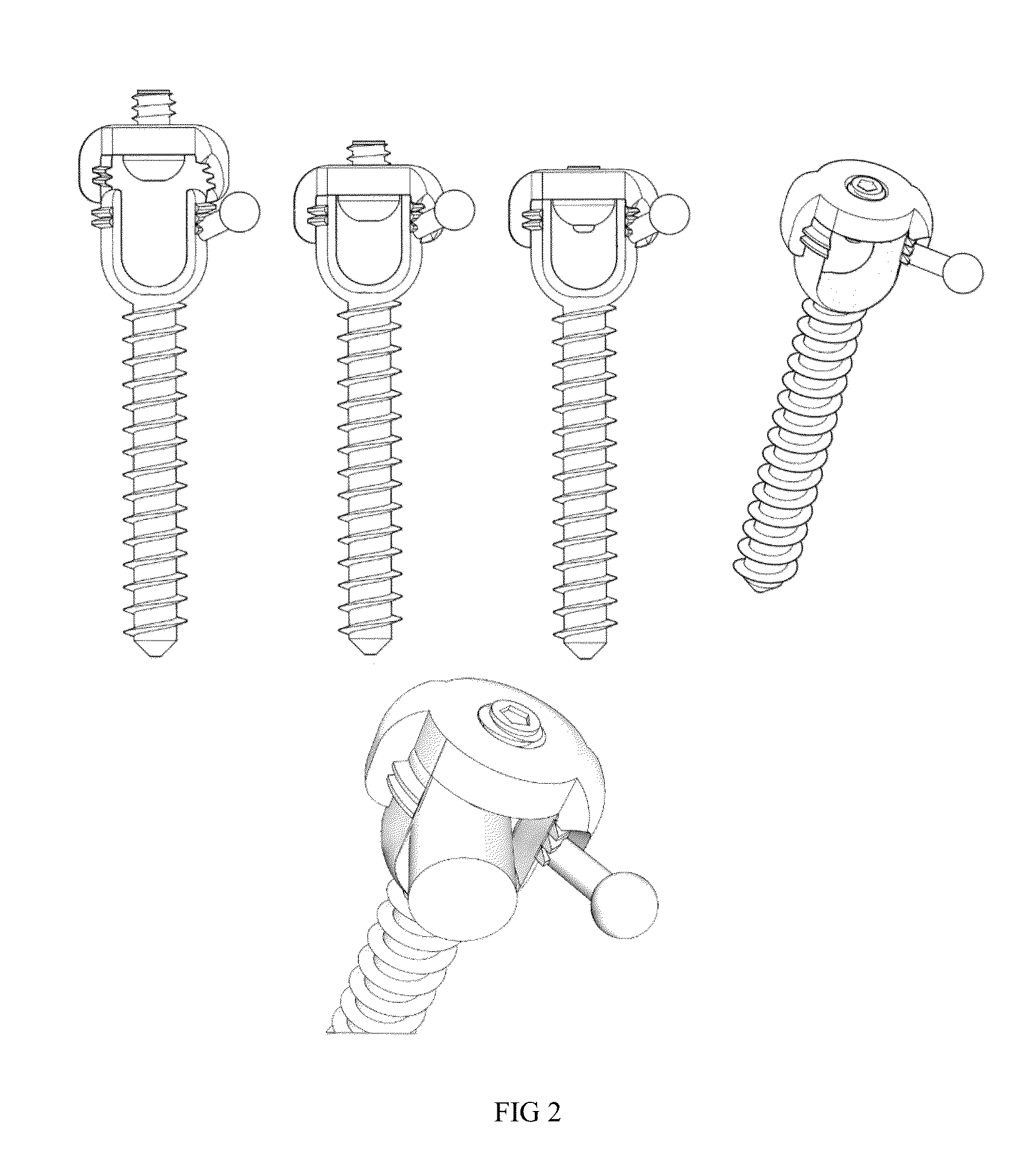
[0067]This invention provides vertebral fixing elements that are to be fixed to the vertebrae and hold firmly onto the bone. The vertebral fixing elements employed can be of any of the types commonly used in spine surgery such as pedicle screws, pedicle or laminar hooks, laminar or spinous process wires, cables, staples, loops or any other type of vertebral fixing element.

[0068]In one exemplary embodiment, normal pedicle screw type vertebral fixing elements are used to hold onto the vertebra because they provide for a solid fixation of the individual vertebra allowing for its adequate three dimensional space mobilization. The conjoined mobilization of two vertebral pedicle screw elements fixed onto the same vertebra with a p...


PUM


Abstract

Devices and corresponding methods for the correction of spinal column deformities, vertebral displacements and for the surgical fixation of the spine including vertebral fixing element(s), vertebral connector element(s), and polyaxial correcting element(s) that can house along its structure varying specifically oriented correction element(s). The polyaxial correcting element(s) are mobilized with the help of correcting force element(s) that induce a three-dimensional mobilization of the polyaxial correcting elements and the vertebrae to which these are attached. Longitudinal spinal fixing element(s) provide for the definitive fixation of the spine. The longitudinal spinal fixing element(s) are joined and fixed to the vertebral fixing element(s) or to permanent vertebral connector element(s). The three-dimensional aspect of the spine is accurately envisioned prior to surgery allowing a caregiver to both create a treatment plan and make intra-operative changes as needed in relation to the correction of the spine.

Description

CROSS-REFERENCE TO RELATED APPLICATIONS[0001]This application claims priority to the U.S. provisional application 61 / 417,496 filed on Nov. 29, 2010 and PCT International Application PCT / US2011 / 061573 filed on Nov. 21, 2011, the contents of which are incorporated in its entirety.FIELD OF THE INVENTION[0002]The present invention relates to the methods and apparatuses employed for the correction of physical deformities of the spine and the methods and apparatuses utilized for the fixation of the spine and its vertebral members. More particularly, this invention specifically aims to correct accurately a misaligned / malaligned spine in a pre-determined and planned way, and to maintain the correction obtained by means of one or more longitudinal spinal fixing elements that are securely fixed to the vertebral members being corrected.BACKGROUND OF THE INVENTION[0003]The Normal and Deformed Spine[0004]The osseous spine is composed of individual vertebral members or vertebrae, which are distri...

Claims


Application Information

Patent Timeline
IPC IPC(8): A61B17/70
CPCA61B17/7049A61B17/7001A61B17/7053A61B17/7032A61B17/7037A61B17/705A61B17/7062A61B17/7077A61B90/50A61B50/15A61B17/7043A61B2017/564A61B2017/681
Inventor PEREIRO DE LAMO, JAVIERRODRIGUEZ OLAVERRI, JUAN CARLOS
Owner PEREIRO DE LAMO JAVIER
Why Eureka
Try Eureka