Method and System for Reducing Peak Load Charge on Utility Bill Using Target Peak Load and Countermeasures

a utility and peak load technology, applied in the field of power management, can solve the problems of reducing the cost savings from peak load management, power generation, and power consumption of site owners, and achieve the effects of reducing the risk of a spike in grid power use, reducing safety margins, and increasing cost savings

Inactive Publication Date: 2013-12-05
NANTENERGY INC
View PDF2 Cites 30 Cited by
  • Summary
  • Abstract
  • Description
  • Claims
  • Application Information

AI Technical Summary

Benefits of technology

[0007]The present invention provides a peak load management system and method that implement countermeasures to reduce the risk of a spike in grid power use above a target peak load due to battery exhaustion. The countermeasures of the present invention eliminate or at least reduce the safety margins built into target peak load peak load management systems and increase the cost savings realized from peak load management.
[0008]In one aspect of the invention, a peak load management system comprises a battery system configured to store power and discharge stored power when actual load exceeds a target peak load; and a peak load management processor operatively coupled with the battery system and configured to continually measure actual load, determine predicted load data based at least in part on past actual load, determine actual load data based at least in part on present actual load, determine a risk of a spike in grid power use above the target peak load due to battery exhaustion based at least in part on the predicted load data and the actual load data and selectively implement one or more countermeasures to reduce the risk based at least in part on a level of the risk.
[0015]In some embodiments, the countermeasures include increasing the target peak load.
[0019]In another aspect of the invention, in a peak load management system comprising a battery system configured to store power and discharge stored power when actual load exceeds a target peak load and a peak load management processor operatively coupled with the battery system, a peak load management method comprises the steps of continually measuring by the management system actual load; determining by the management system predicted load data based at least in part on past actual load; determining by the management system actual load data based at least in part on present actual load; determining by the management system a risk of a spike in grid power use above the target peak load due to battery exhaustion based at least in part on the predicted load data and the actual load data; and selectively implementing by the management system one or more countermeasures to reduce the risk based at least in part on a level of the risk.

Problems solved by technology

A suboptimal target peak load setting can result from errors in estimating the site owner's power consumption, power generation (e.g., solar output), or both.
If the target peak load is set too low, the stored power in the battery system may be exhausted before the measured load falls below the target peak load and the use of grid power may spike above the target peak load, decimating the cost savings from peak load management.
On the other hand, if the target peak load is set too high, the use of grid power is permitted to rise above a level that could be successfully offset the battery system, resulting in an underutilization of the battery system that unduly limits the cost savings from peak load management.
Unfortunately, building a safety margin into the target peak load does not completely eliminate the risk of a spike above the target peak load due to battery exhaustion.
For example, as shown in FIG. 2, if the measured (actual) load substantially exceeds the predicted load on the “worst case” day of the billing period, the stored power in the battery system may be exhausted before the measured load falls below the target peak load, causing the use of grid power to spike above the target peak load despite the built-in safety margin.
Such a spike on a single day of the billing cycle can cause a significant increase in the peak load component of the site owner's utility bill and render the peak load management system largely ineffectual.
Moreover, building a safety margin into the target peak load has further downside in allowing the peak use of grid power to rise above a level which could potentially be successfully offset by the battery system, which reduces the cost savings achieved by the management system.

Method used


Image

  • Method and System for Reducing Peak Load Charge on Utility Bill Using Target Peak Load and Countermeasures
  • Method and System for Reducing Peak Load Charge on Utility Bill Using Target Peak Load and Countermeasures
  • Method and System for Reducing Peak Load Charge on Utility Bill Using Target Peak Load and Countermeasures

Examples


Embodiment Construction

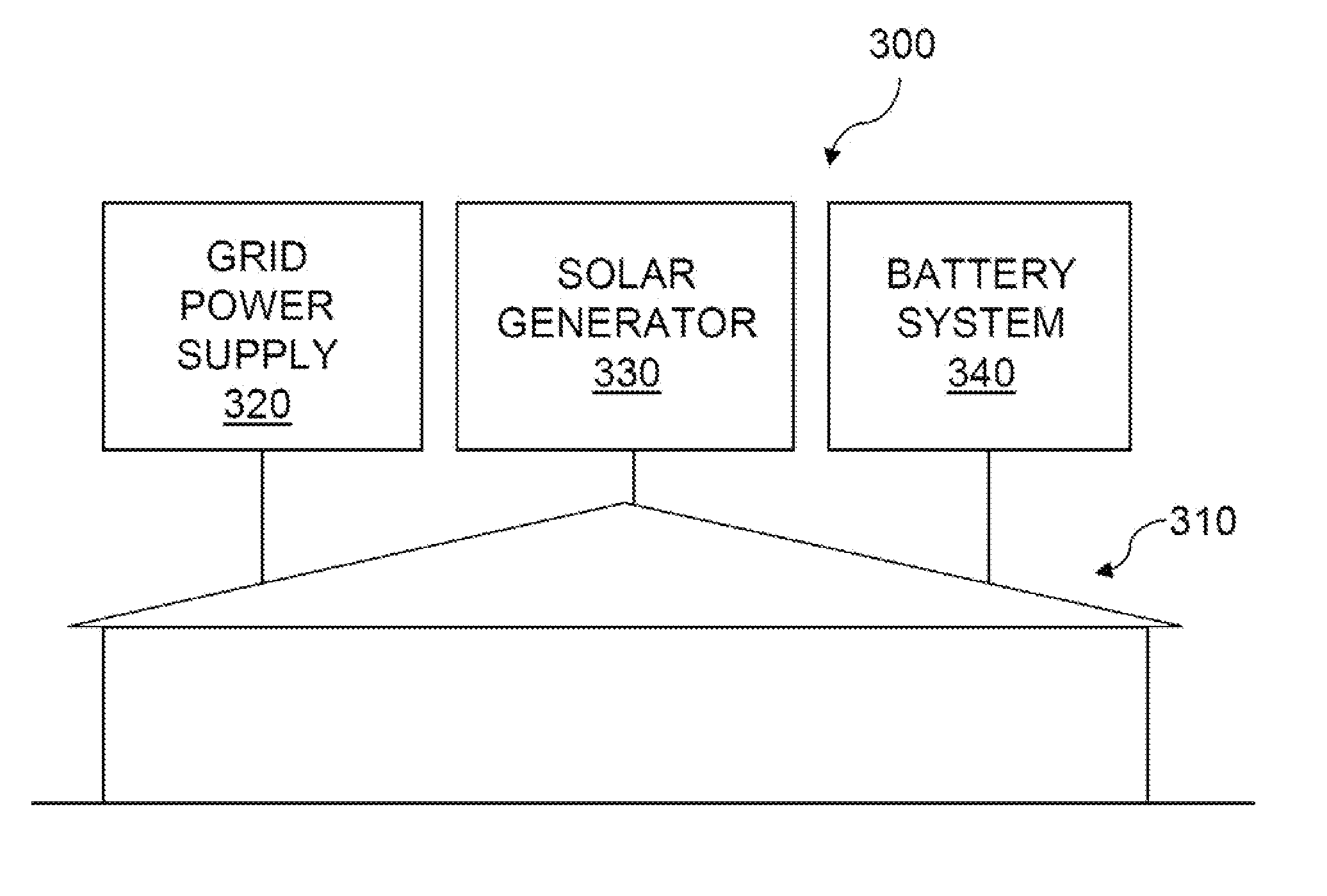
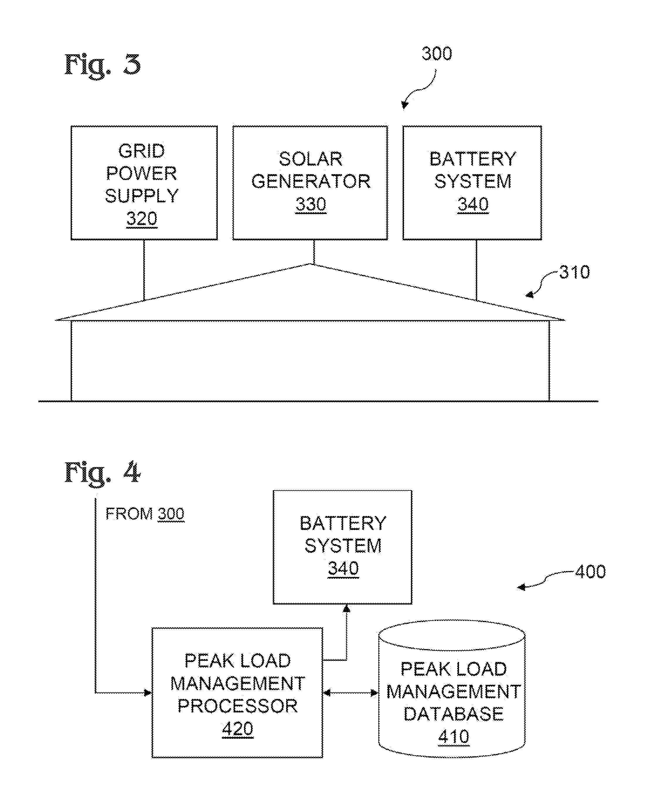
[0038]FIG. 3 shows a power system 300 for a site 310 operated by a site owner who is a customer of an electric utility. Power system 300 includes multiple power sources that supply power to site 310 at various times and in various amounts. The power sources include a grid power supply 320 drawn on the electric utility. The electric utility that supplies the grid power bills the site owner periodically, such as monthly, for grid power. These periodic electric utility bills include a peak load component that assesses the site owner a charge based on the peak usage of grid power at site 310 during the billing period. The power sources also include a solar generator 330 that supplies power to site 310 during daylight hours, at least partially offsetting the use of grid power. The power sources further include a battery system 340 that stores power and discharges stored power to site 310 only when actual load drawn by site 310 exceeds a target peak load. Referring now to FIG. 3 and FIG. ...


PUM


Abstract

A peak load management system and method take countermeasures to reduce the risk of a spike in grid power use above a target peak load due to battery exhaustion. The countermeasures replace or at least reduce the safety margins built into target peak load peak load management systems and increase the cost savings realized from peak load management.

Description

BACKGROUND OF THE INVENTION[0001]The present invention relates to power management and, more particularly, managing the peak load drawn by a site owner on an electric utility to reduce the site owner's utility bills.[0002]Utility bills often include a peak load component that assesses a site owner a charge based on the peak usage of grid power at the site during a multi-day billing period.[0003]To reduce the amount of the peak load charge, it is known to deploy a peak load management system that continually measures load at the site throughout the billing period and limits the use of grid power to a target peak load. The target peak load is often statically configured for the billing period, either manually or by an algorithm running on the management system. Whenever the measured load reaches the target peak load during the billing period, the management system discharges stored power from a battery system to keep the use of grid power from exceeding the target peak load. Once the ...

Claims


Application Information

Patent Timeline
Patent Type & Authority Applications(United States)
IPC IPC(8): G06F1/26
CPCH02J3/32H02J2300/24H02J3/381Y02E10/56Y04S20/222Y02B70/3225H02J2300/22Y02E70/30
Inventor MANSFIELD, CARL
Owner NANTENERGY INC
Why Eureka
Try Eureka