Data reader platter with integral features delineating a data-reading sweep region

a data reader and sweep region technology, applied in the field of system and method of data reading, can solve the problems of falling off the scanner, occlude the scan volume, and easily wear off of indicators, and achieve the effect of reducing reflection and reducing specular reflection

Active Publication Date: 2013-12-12
DATALOGIC ADC
View PDF16 Cites 6 Cited by
  • Summary
  • Abstract
  • Description
  • Claims
  • Application Information

AI Technical Summary

Benefits of technology

[0008]The present disclosure describes a data reader platter suitable for reducing reflection, and it describes platters that convey to a user of the data reader a region where items bearing optical codes should be swept through a read zone, i.e., a path across the read zone where successful data reads will (or will not) likely occur. Systems include a platter (with or without a scale) that has integral features adjacent a centrally located platter window and configured to delineate the contours of a preferred data-reading sweep region. In one embodiment, the integral features are in the form of a graphic etch pattern of circles or other etched shapes at etch depths resistant to wear. In another embodiment, the integral features are in the form of depressions or other features that inhibit or dissuade a user from sliding items on the platter and thereby indicate keep-out zones delineating a preferred data-reading sweep region of the read zone that is typically located above a central portion of the platter. The present inventors have recognized that, in some instances, illumination is reflected from surrounding surfaces of the data reader and inadvertently toward a customer or checkout clerk operating the data reader. The integral features may include surface treatments or features that reduce specular reflection otherwise reflected by stainless steel or similar surfaces.

Problems solved by technology

These indicators easily wear off, occlude the scan volume, or simply fall off the scanner over time.
In some instances, the illumination can be a distraction to users.

Method used


Image

  • Data reader platter with integral features delineating a data-reading sweep region
  • Data reader platter with integral features delineating a data-reading sweep region
  • Data reader platter with integral features delineating a data-reading sweep region

Examples


Embodiment Construction

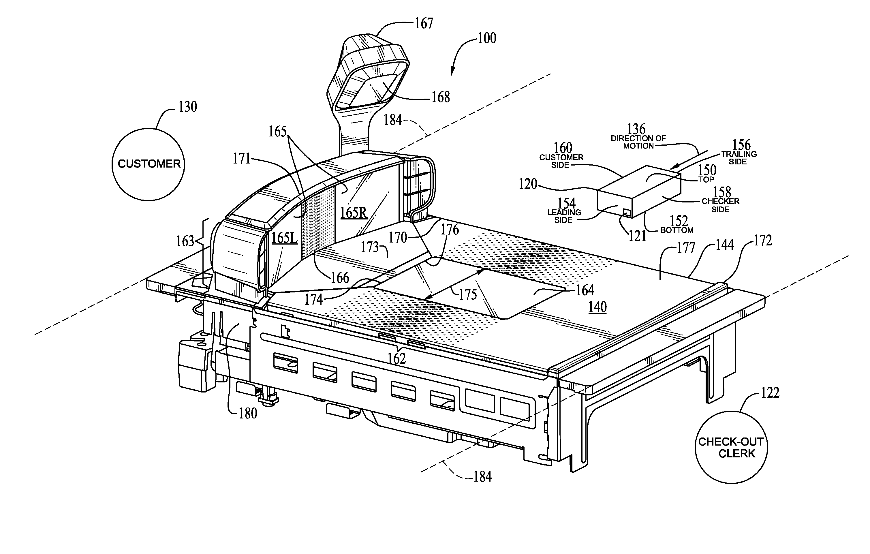
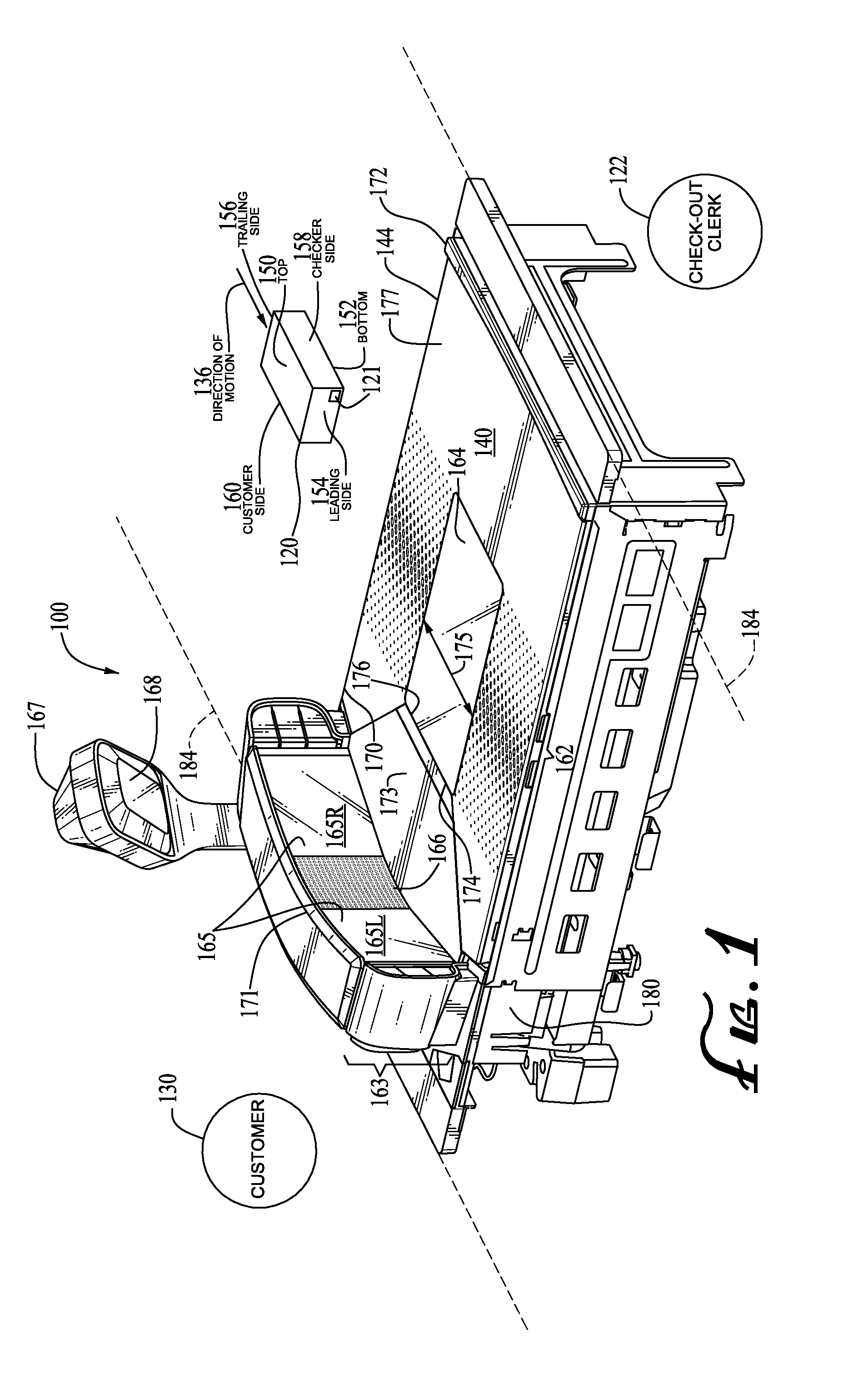
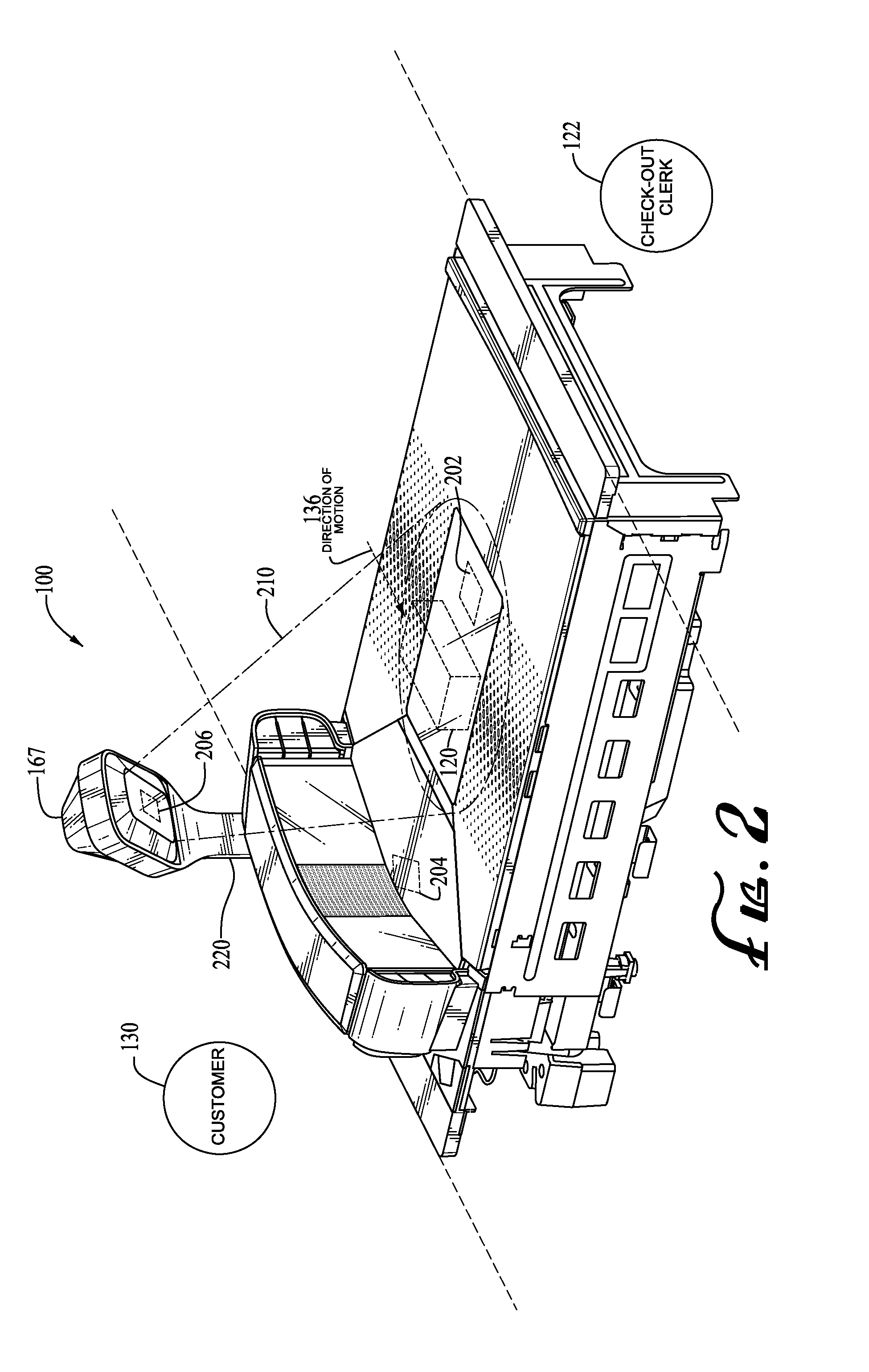
[0020]For efficient use of a data reader, it is desirable to maximize a first-pass read rate by increasing the probability that an item will have its optical code successfully read on a single data-reading sweep across a read zone. For purposes of the present description, a region of the read zone that may tend to maximize a first-pass read rate for most items (and typically produces a successful read) is referred to as a preferred data-reading sweep region of the read zone.

[0021]For various reasons, the periphery of a preferred data-reading sweep region, as well as its general spatial location and dimensions with respect to a data reader, may be neither intuitive nor obvious to a user passing items through a read zone of the data reader. First, the read zone itself may be formed from one or more imaging devices that occasionally have partially overlapping read volumes configured to simultaneously read several sides of the item. For example, in both laser-based and imager-based type...


PUM


Abstract

Disclosed is a data reading system that includes a housing and a platter window for concealing a data reader configured to read an optical code borne by an item transported through a read zone. The read zone is defined at least in part by the platter window. The data reading system also has a platter supportable on the housing that encompasses the platter window. The platter includes a first integral feature and a second integral feature bordering opposing peripheral sides of the platter window. The first and second integral features cooperatively delineate a preferred data-reading sweep path through the read zone.

Description

RELATED APPLICATION[0001]This application claims the benefit under 35 U.S.C. §119(e) of U.S. Provisional Patent Application No. 61 / 657,690, filed Jun. 8, 2012, which is hereby incorporated by reference in its entirety.BACKGROUND INFORMATION[0002]The field of this disclosure relates generally to systems and methods for data reading, and more particularly, to checkout station systems incorporating covers or weigh scale platters configured for use with data readers.[0003]There are many types of optical codes that use various symbologies, including one-dimensional barcodes, such as a Universal Product Code (UPC) and EAN / JAN codes; stacked codes, such as PDF417; and two-dimensional codes, such as Maxicode codes. Such optical codes have widespread applications. For example, optical codes can be used to identify a class of items (e.g., merchandise) or unique items (e.g., patents). Thus, optical codes are found on a wide variety of items and objects, such as retail goods, company assets, an...

Claims


Application Information

Patent Timeline
Patent Type & Authority Applications(United States)
IPC IPC(8): G06K7/015G06V30/224
CPCG06K7/015G06K7/10831G06K7/1096G06K7/10821
Inventor THOMPSON, RYAN B.NEWMAN, DAVID J.MCQUEEN, ALEXANDER M.LENART, CHRISTOPHER N.
Owner DATALOGIC ADC
Why Eureka
Try Eureka