
Buoyancy system

a buoyancy/floatation system and airframe technology, applied in the field of buoyancy systems, can solve the problems of increasing fuel consumption, increasing maintenance hours and additional costs, and inconvenient operation, and achieve the effect of sufficient tim

Inactive Publication Date: 2013-12-12
LYONS TIM
View PDF11 Cites 22 Cited by
  • Summary
  • Abstract
  • Description
  • Claims
  • Application Information

AI Technical Summary

Benefits of technology

The buoyancy system is designed to help aircraft occupants safely get out of an aircraft that has landed, crashed, or ditched into a body of water. It is also meant to assist in rescuing the aircraft and any valuable materials on it, assisting subsequent investigation of the accident.

Problems solved by technology

There are inherent difficulties and limitations associated with current in-built buoyancy / floatation systems fitted to aircraft, which are typically permanently attached to the aircraft.
Permanently fitted buoyancy / floatation systems add significant weight to the airframe, increasing fuel consumption, maintenance hours and additional cost whilst reducing endurance, payload and the overall capability of the aircraft.
For these reasons, incorporating permanent buoyancy / floatation systems into multi role aircraft is often deemed not feasible.
Hence many multi role aircraft do not have emergency buoyancy / floatation systems fitted.
In most cases such aircraft are not fitted with a system that can provide sufficient buoyancy to keep the aircraft afloat, which is a problem should they ditch or crash into water.
This poses a significant risk to the aircraft and their crew when operating over water.
Buoyancy and floatation systems currently fitted to marine helicopters are generally heavy in weight, reducing the aircraft's capability and performance.
As most helicopters have a high centre of gravity due to the positioning of the engine(s), transmission and rotor hub, the inflated inflatable buoyancy bags, tend to cause the aircraft to overturn and sit upside down in the water, presenting disorientation problems to the submerged crew and passengers, and increasing the difficulty to rescue the crew and passengers.

Method used


Image

  • Buoyancy system
  • Buoyancy system
  • Buoyancy system

Examples


Embodiment Construction

[0075]The present invention has many applications across numerous aircraft and provides significant advantages over the prior art.

[0076]The below embodiments discuss applications in which a helicopter ditches or crashes into a body of water. However, it is to be understood that the present invention may be fitted to other type of aircraft, those applications being covered by the present invention.

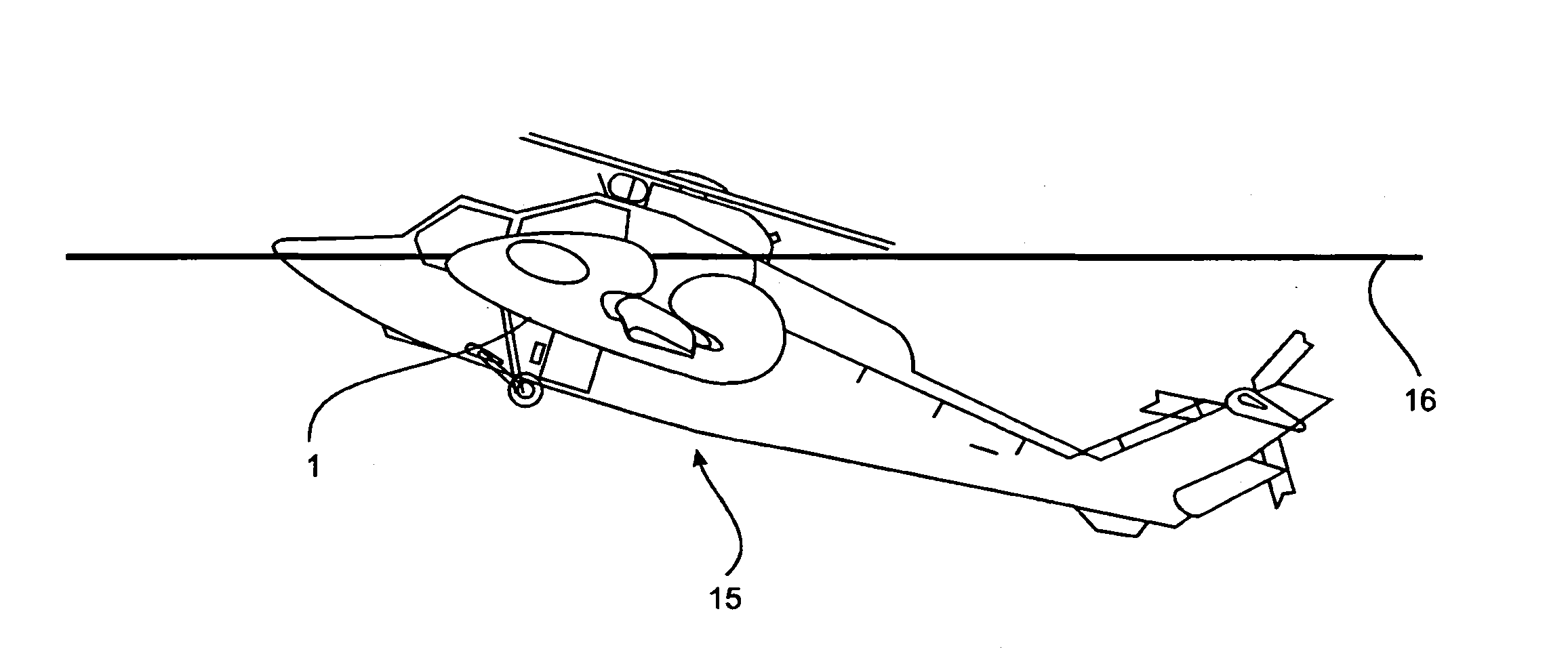
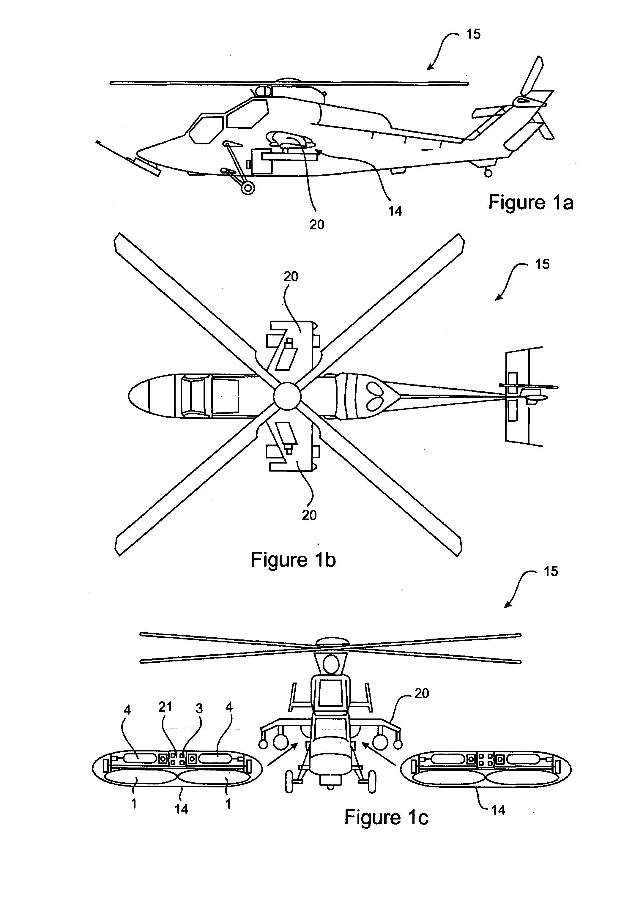
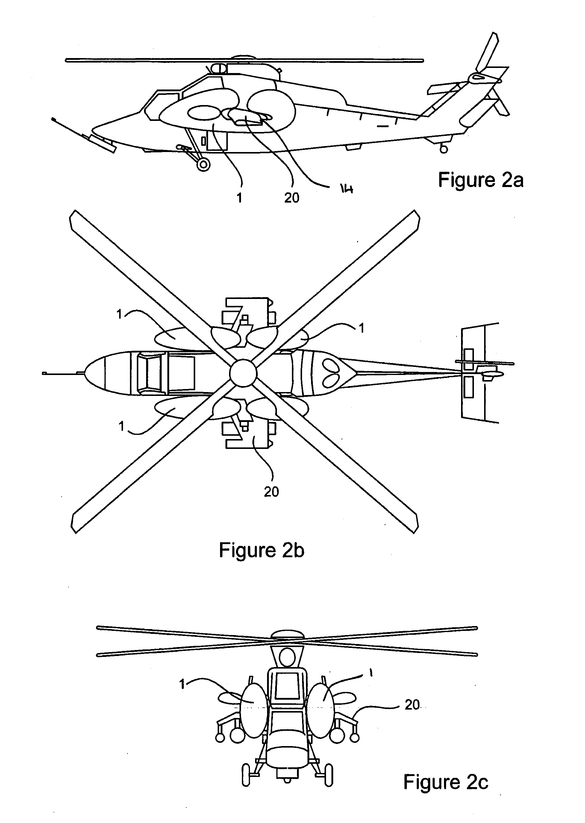
[0077]The invention according to the various embodiments is in the form of a buoyancy system 14 fitted to an helicopter 16 whereby, post activation, the buoyancy system 14 will keep the helicopter 15 afloat and maintain it in a substantially upright orientation near the surface of a body of water 16.

[0078]The buoyancy system 14 may quickly be removed from and easily attach to an helicopter 15, depending on whether the helicopter 15 will be flying over water. This ensures the weight of the helicopter can be optimised when flying over land where a buoyancy system is not required.

[0079]The buo...


PUM


Abstract

The present invention provides an aircraft buoyancy system (14) for providing positive buoyancy to an aircraft (15) to keep it afloat at the surface of a body of water (16) after crashing, ditching or landing into a body of water (16). The aircraft buoyancy system (14) comprises at least one inflatable body (1) which, when inflated, increases the buoyancy of the aircraft (14), and a gas generation system (4) to inflate the at least one inflatable body (1). The aircraft buoyancy system (14) also comprises a sensor and activation system (3) to activate the gas generation system (4). Upon activation of the sensor and activation system (3) the gas generation system (4) causes a gas to flow to the at least one inflatable body (1), causing the aircraft (15) to float and remain at the surface of a body of water (16).

Description

FIELD OF THE INVENTION[0001]The present invention generally relates to a buoyancy system for keeping aircraft afloat. In particular, the present invention provides a buoyancy system for keeping an aircraft upright, upon landing, crashing or ditching into a body of water.BACKGROUND ART[0002]There are inherent difficulties and limitations associated with current in-built buoyancy / floatation systems fitted to aircraft, which are typically permanently attached to the aircraft. Permanently fitted buoyancy / floatation systems add significant weight to the airframe, increasing fuel consumption, maintenance hours and additional cost whilst reducing endurance, payload and the overall capability of the aircraft. For these reasons, incorporating permanent buoyancy / floatation systems into multi role aircraft is often deemed not feasible. Hence many multi role aircraft do not have emergency buoyancy / floatation systems fitted.[0003]Multi role aircraft such as military Blackhawk helicopters are oft...

Claims


Application Information

Patent Timeline
IPC IPC(8): B64C25/56
CPCB64C25/56B64C27/006B64C2025/325B64D2201/00
Inventor LYONS, TIM
Owner LYONS TIM
Learn More