Arrangement and method for manufacturing a wind turbine blade

a technology of wind turbine blades and manufacturing methods, which is applied in the manufacture of final products, dough shaping, manufacturing tools, etc., can solve the problems of high cost and time-consuming process of manufacturing slugs and outer molds

Inactive Publication Date: 2013-12-12
SIEMENS AG
View PDF6 Cites 4 Cited by
  • Summary
  • Abstract
  • Description
  • Claims
  • Application Information

AI Technical Summary

Problems solved by technology

Consequently, manufacturing the slug and outer mold is an expensive and time consuming process.

Method used


Image

  • Arrangement and method for manufacturing a wind turbine blade
  • Arrangement and method for manufacturing a wind turbine blade
  • Arrangement and method for manufacturing a wind turbine blade

Examples


Embodiment Construction

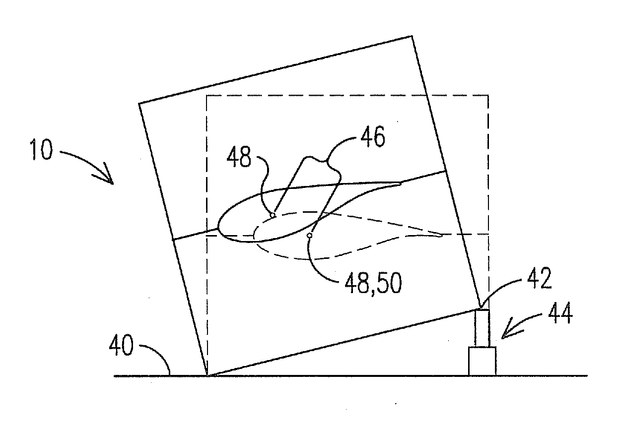
[0018]The inventor has devised a mold assembly for a closed mold process where a single outer mold can be used to define more than one outer blade geometry. As a result; one outer mold can be formed from one slug, and the one outer mold can be used to form a variety of blades with differing outer geometries. In addition, the inner geometry of the blade can be changed as desired to accommodate whatever outer blade geometry is selected. By utilizing a single outer mold for more than one blade geometry, the present invention facilitates a reduction in the cost and time needed to produce a new blade design, and may be used to effectively correct a mold's geometric design post-production.

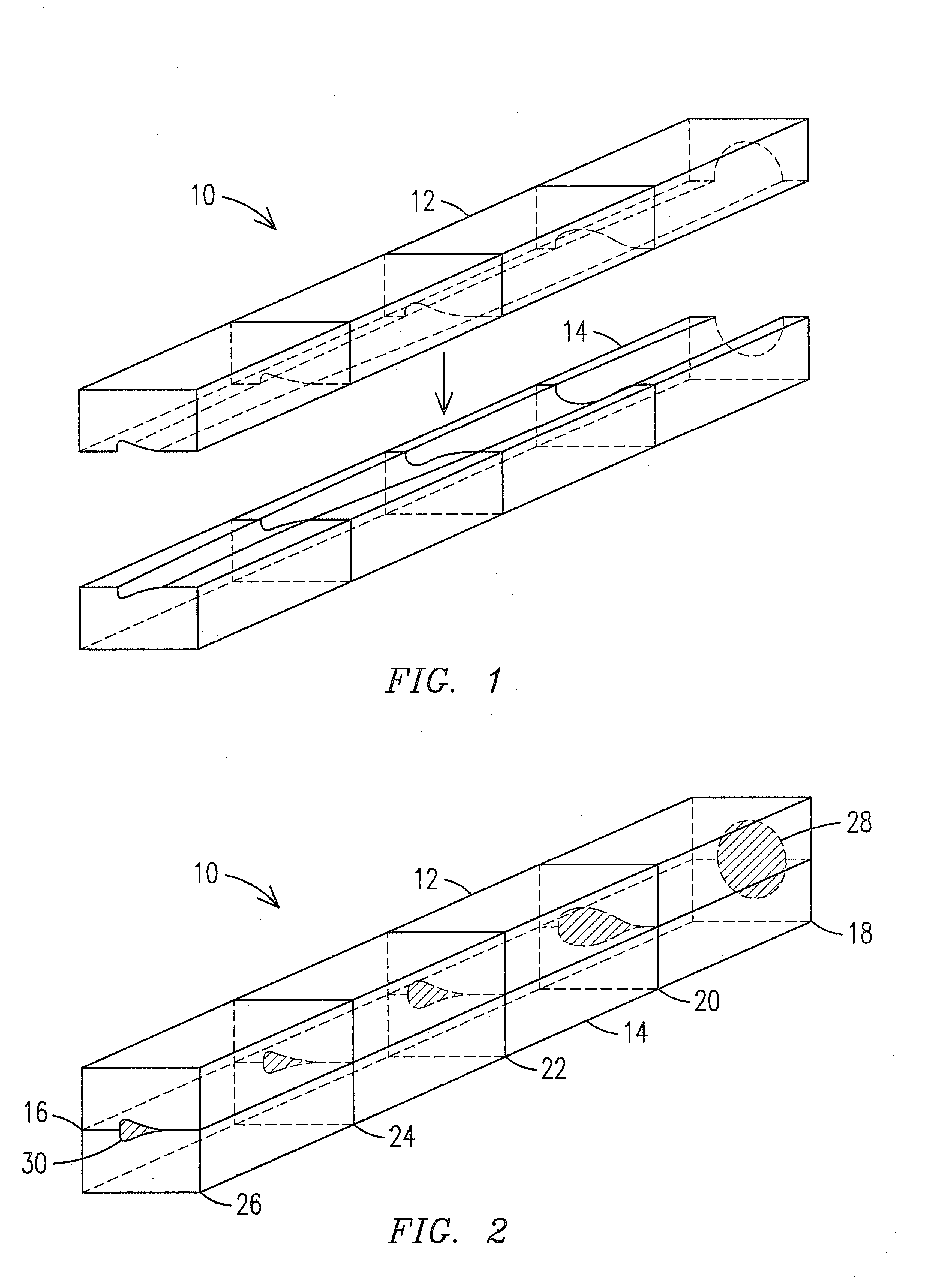
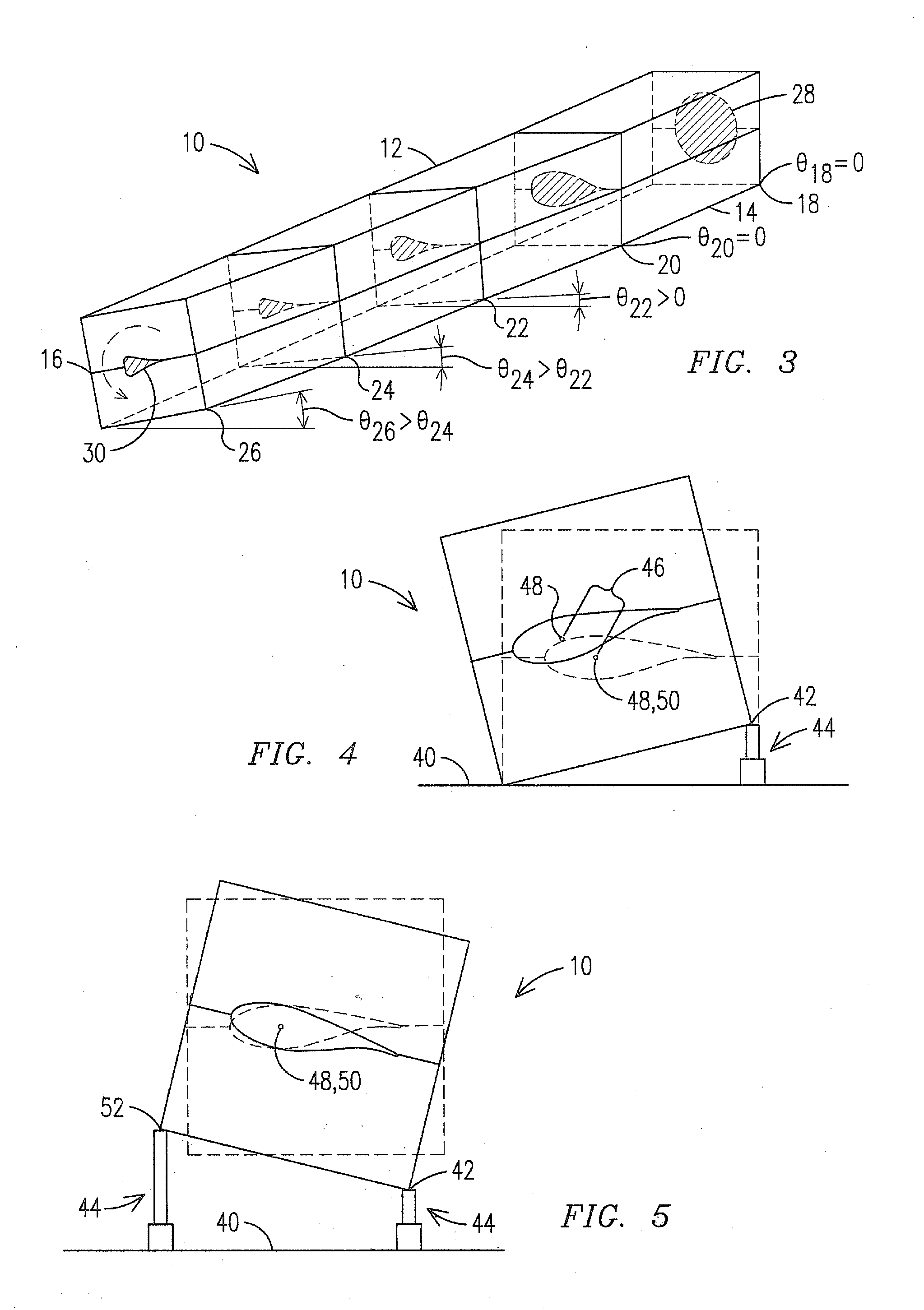
[0019]As shown in FIG. 1, an outer mold may 10 may include a first half 12 and a second half 14. In an exemplary embodiment shown in FIG. 2 the first half 12 and the second half 14 may be joined at a joint 16. Within the outer mold 10 an outer geometry is indicated in the various cross sections 18, 20, 2...


PUM

PropertyMeasurementUnit
lengthaaaaaaaaaa
shapeaaaaaaaaaa
flexibleaaaaaaaaaa

Abstract

A closed mold arrangement for manufacturing a wind turbine blade, including: a closed outer mold (10); a mechanism (44) to selectively flex the outer mold (10) across a range of outer geometries; and a first inner mold (92, 120). The first inner mold (92, 102, 120, 140) is used in the closed outer mold (10) when the closed outer mold (10) is in a first outer geometry and thereby defines a first blade geometry. Alternatively a second inner mold (102, 140) is used in the closed outer mold (10) when the closed outer mold (10) is flexed to a second outer geometry different than the first outer geometry and thereby defines a second blade geometry.

Description

FIELD OF THE INVENTION[0001]The invention relates generally to the manufacturing of wind turbine blades. In particular, the invention relates to a closed molding process to make blades with differing geometries using a single outer mold.BACKGROUND OF THE INVENTION[0002]Wind turbine blades are often formed using a closed mold process where a composite material is formed into shape between an inner mold and an outer mold. Often the composite material includes fiberglass matte material which is positioned between the inner mold and outer mold. Subsequently, resin material is introduced into the space between the inner and outer molds to infuse the fiberglass matte. In certain manufacturing processes two blade halves are independently formed and subsequently joined to form the complete blade. In one manufacturing process the entire blade is formed at once.[0003]In order to make a blade outer mold, a slug is manufactured by, for example, a CNC machining process to match a desired final o...

Claims


Application Information

Patent Timeline
Patent Type & Authority Applications(United States)
IPC IPC(8): B29C67/00B29C33/38
CPCB29C33/306B29C33/308B29C33/50B29L2031/085Y02P70/50
Inventor OBRECHT, JOHN M.
Owner SIEMENS AG
Why Eureka
Try Eureka