
Passive redirection device for consumption meter communication

a technology of consumption meters and redirections, applied in the direction of passive radio relay systems, radio relay systems, transmission systems, etc., can solve the problems of complex mounting of repeaters, insufficient communication range for application to operate reliably, complex, and energy-consuming solutions, etc., to achieve low cost, robust

Inactive Publication Date: 2013-12-12
APATOR MIITORS APS
View PDF6 Cites 12 Cited by
  • Summary
  • Abstract
  • Description
  • Claims
  • Application Information

AI Technical Summary

Benefits of technology

The invention is a device that helps improve radio communication from a utility meter that is placed in a poor position. It is affordable, durable, and easy to install. Its purpose is to improve the efficiency and reliability of wireless communication in such situations.

Problems solved by technology

In some situations the communication range may be insufficient for the application to operate reliably.
Most often this is the case, when the meter is placed in non-optimal positions such as a pit in the ground, a cellar, or in other positions where the communication range is limited by structures between the meter and the communication device.
Although this solution increases the range considerably, it has the drawback that it is a complex, expensive, and energy consuming solution.
These solutions protect the sensitive electronic circuitry to some degree, but the mounting of the repeater is complicated, and the antenna position is less optimal.
In addition the lifetime of the repeater in these solutions is limited due to the embedded battery power source.
These solutions have the drawbacks that they are complex and expensive, energy consuming, and have limited lifetimes.

Method used


Image

  • Passive redirection device for consumption meter communication
  • Passive redirection device for consumption meter communication
  • Passive redirection device for consumption meter communication

Examples


Embodiment Construction

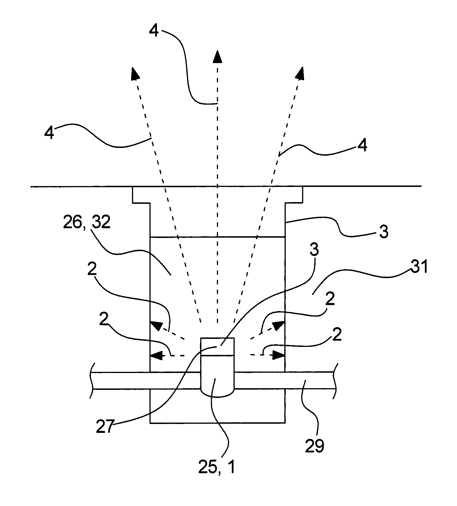
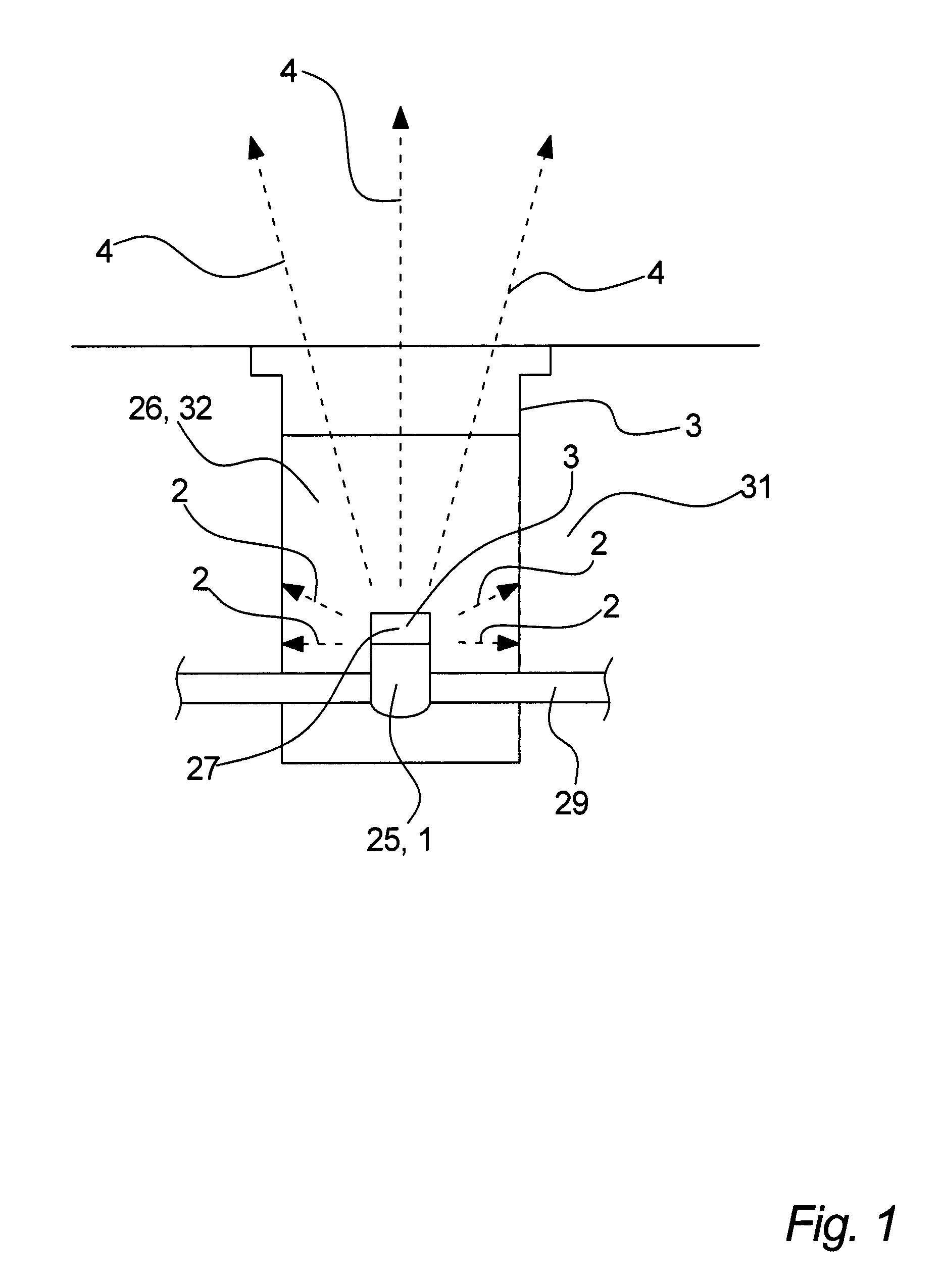
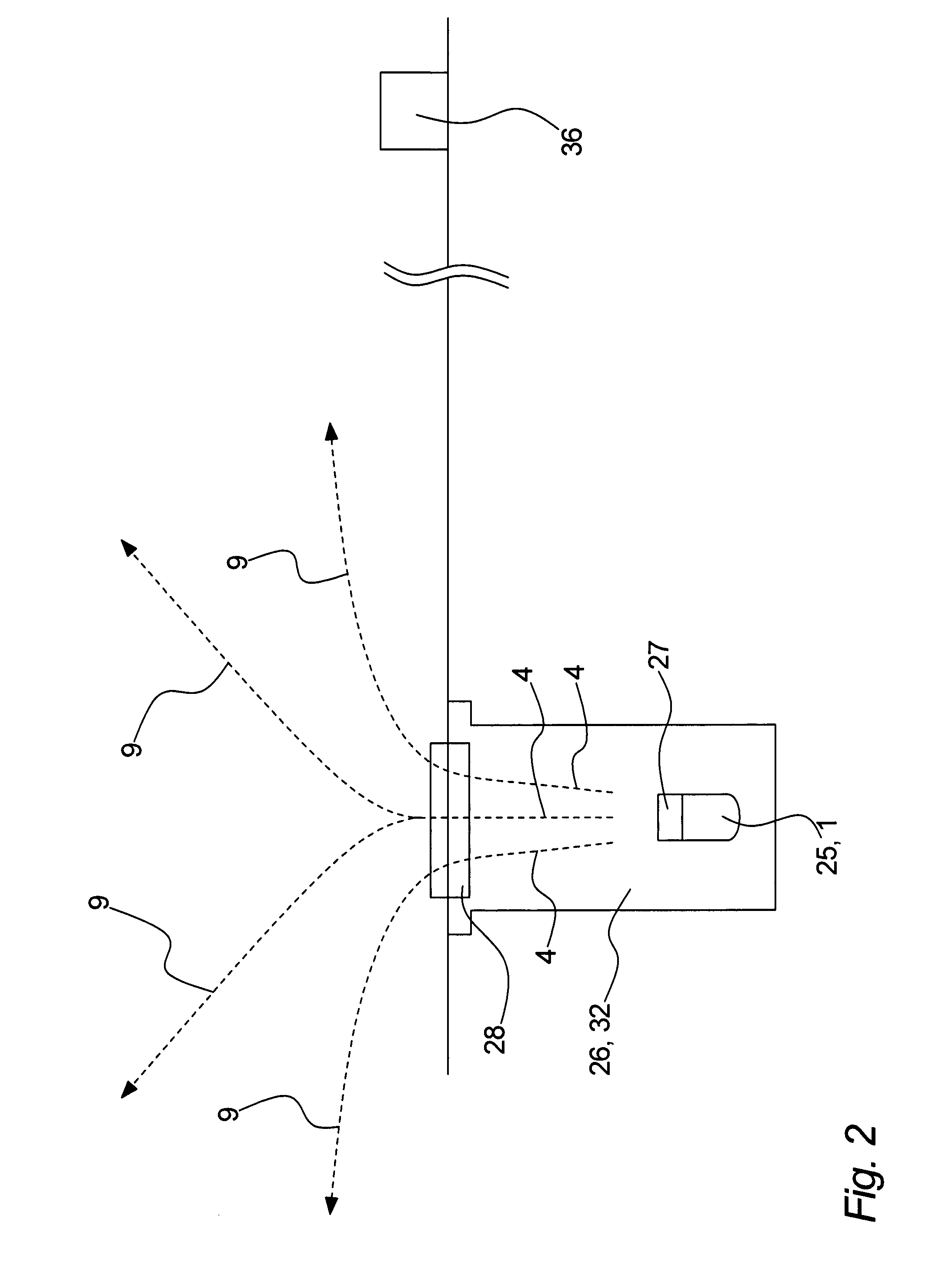
[0087]Referring to FIG. 1, a data collection unit 25, such as a utility meter 1, is situated in a hollow shaft 26, such as a meter pit 32, is illustrated. As it can be seen from FIG. 1, the data collection unit 25 is positioned in the lower part of the hollow shaft 26. The data collection unit 25 comprises a radio transmitter or radio emitter 27. The hollow shaft 26 may e.g. be a meter pit 32 or a utility shaft 12. Furthermore such a data collection unit 25 may be connected to a part of a utility system 29. The hollow shaft 26 may be comprise a upper end closing part 30, which seals off the hollow shaft 26 from the surroundings. The data collection unit 25 may collect data from the part of the utility system 29, which it is connected to. Such collected data may e.g. be data representing consumption of e.g. gas, water, heat provided by the utility system. As it is illustrated on FIG. 1, the radio emitter 27 emits a radio signal in the form of radio waves 2, 4. While some radio waves ...


PUM


Abstract

A method of transmitting and redirecting a radio signal using a data transmission system, the data transmission system including a data collection unit, a radio transmitter being connected to the data collection unit, and a redirection device being arranged at the top of a hollow shaft, the radio transmitter and the data collection unit being arranged in a lower part of the hollow shaft, the method including the steps of the radio transmitter transmitting the radio signal representative of measurement data from the data collection unit, and the redirection device redirecting the radio signal to be received at a communication device. The invention furthermore relates to a data transmission system and a redirection device adapted for operating in accordance with the above mentioned method.

Description

TECHNICAL FIELD[0001]The present invention relates to redirection device for redirection a radio wave signal from a data acquisition device, such as a utility meter, to a communication device and a method for transmitting and redirecting said radio signal by means of said redirection device.BACKGROUND OF THE INVENTION[0002]Consumption meters communicating by the emission of modulated electromagnetic waves at radio frequencies is a well-known technology for reading the status of such meters. The method allows remote reading in several different topologies, and a very long communication range is often feasible, depending on the parameters of the system. The parameters influencing the range are, among others: transmission frequency, bit transmission rate, message length, modulation scheme, error correction, antenna size, antenna directivity, transmission power, receiver noise level, receiver selectivity, interference from other sources, and finally reflections and absorption from struc...

Claims


Application Information

Patent Timeline
Patent Type & Authority Applications(United States)
IPC IPC(8): G01D4/00
CPCG01D4/002H01Q15/08H04B7/145H01Q19/08H01Q1/2233H01Q1/04Y02B90/20Y04S20/30H01Q1/225
Inventor DRACHMANN, JENS
Owner APATOR MIITORS APS
Learn More