
Radio communication system, radio communication method, radio transmitter and radio receiver

a radio communication system and communication method technology, applied in the field of radio communication systems, radio communication methods, radio transmitters and radio receivers, can solve problems such as difficulty in employing channel estimation and decrease in transmission rate (throughput), and achieve the effect of reducing throughpu

Inactive Publication Date: 2010-03-30
FUJITSU LTD
View PDF9 Cites 75 Cited by
  • Summary
  • Abstract
  • Description
  • Claims
  • Application Information

AI Technical Summary

Benefits of technology

The present invention aims to solve the problem of decreased throughput in a radio communication system where a MIMO and an AAA system are used without a common pilot. The invention proposes a solution by employing a common pilot for both systems, which allows for the coexistence of MIMO and AAA without causing a decrease in throughput. The invention also includes methods for producing and transmitting pilot signals, as well as methods for estimating the channel on the transmission antenna. The technical effects of the invention include improved throughput, reduced interference between pilot signals, and improved signal quality.

Problems solved by technology

When the MIMO pilot signal is used for the AAA, since a data unit produces and transmits a beam with directivity, different propagation paths are employed between the pilot signal and the data signal and, hence, difficulty is encountered in employ it for the channel estimation.
However, this leads to a decrease in transmission rate (throughput) and requires the information on the added pilot signal and the processing therefor.

Method used


Image

  • Radio communication system, radio communication method, radio transmitter and radio receiver
  • Radio communication system, radio communication method, radio transmitter and radio receiver
  • Radio communication system, radio communication method, radio transmitter and radio receiver

Examples


example 3 (

[0142][D] Concrete Example 3 (Mode of Application to Radio Communication System)

[0143]Although the aforesaid concrete examples 1 and 2 relate to the configurations of the transmitter 1 and the receiver 2 (2A to 2G), in this concrete example 3, a description will be given of a mode of application to a radio communication system. FIGS. 7 and 8 are illustrations of examples of application to a radio communication system (mobile communication system). The description will be given of a case of down-link data transmission. That is, a base station side serves as the transmitter 1 while a terminal side acts as the receiver 2.

[0144](D1) FIG. 7 shows a system configuration designed to use the MIMO mode and the AAA mode separately according to application environments.

[0145]In FIG. 7, three cellular cells 100 adjacent to each other are formed by three base stations (transmitters) 1A, 1B and 1C adjacent to each other, and isolated cells 200 at enclaves with respect to the cellular cells 100 ar...


PUM


Abstract

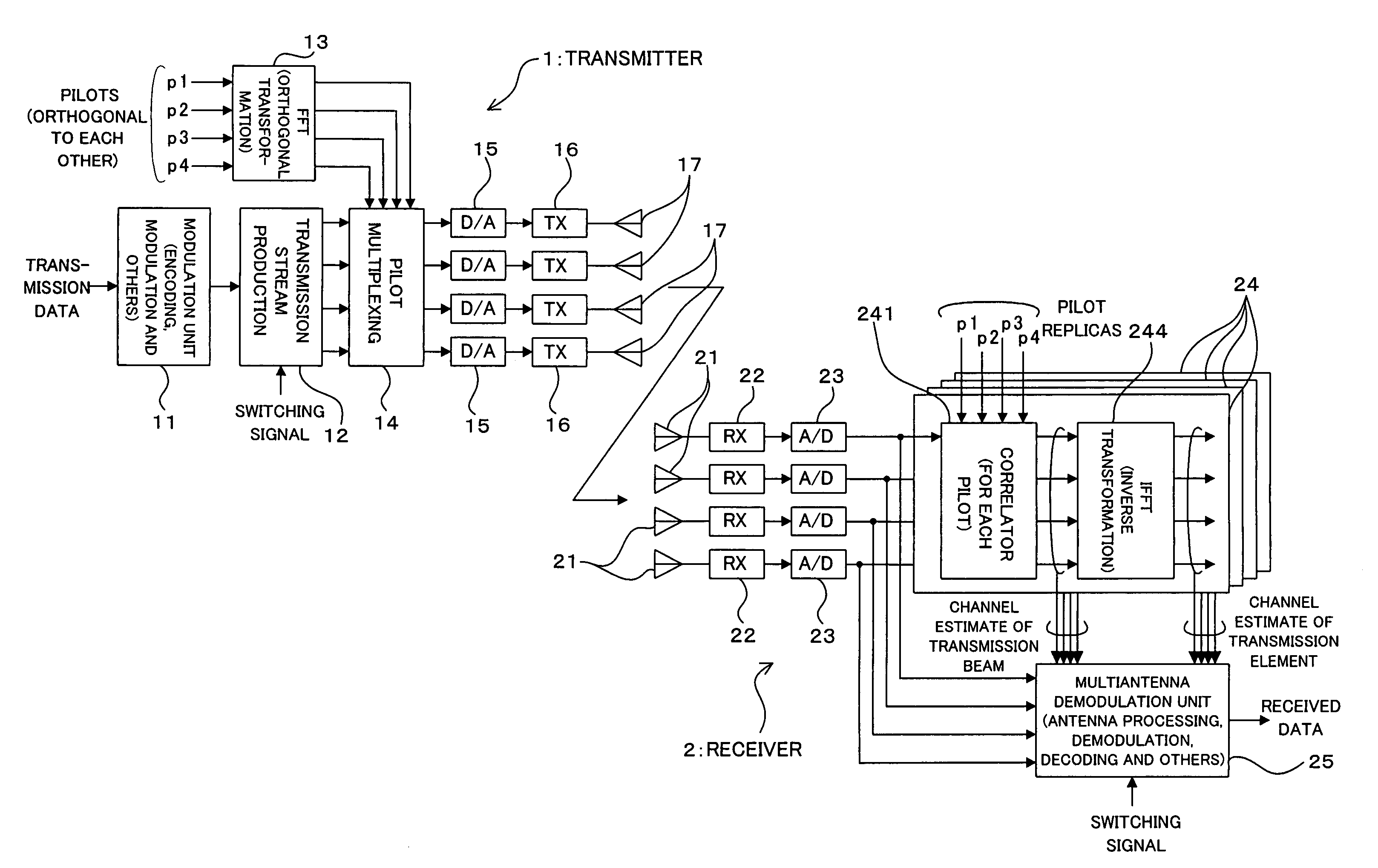
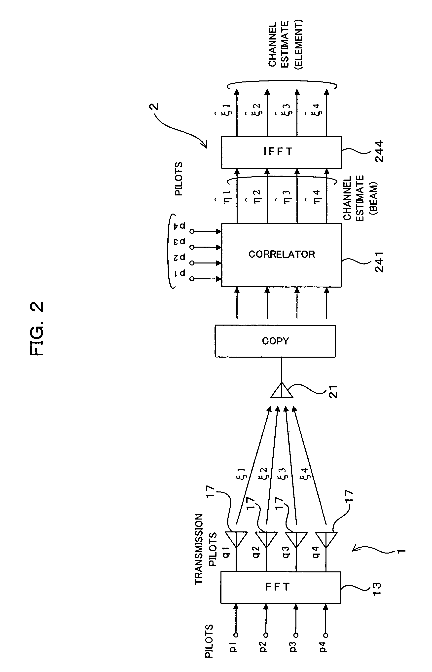
A radio transmitter includes an orthogonal transformation unit for carrying out an orthogonal transformation on pilot signals having orthogonal relation to each other between transmission antennas and a pilot multiplexing unit multiplexing the pilot signals and transmission data, and a radio receiver includes a channel estimation unit obtaining a channel estimate of a directive multibeam for each of reception antennas, an inverse transformation unit carrying out an inverse transformation of the orthogonal transformation on the obtained channel estimate and a received signal processing unit selectively conducting first processing based on the beam channel estimate in the first mode or second processing based on the channel estimate obtained by the inverse transformation unit in the second mode. This commonizes a common pilot for MIMO (second mode) and individual pilots for AAA (first mode), thus realizing the coexistence of MIMO and AAA without leading to a reduction of throughput.

Description

CROSS REFERENCE TO RELATED APPLICATIONS[0001]This application is based on and hereby claims priority to Japanese Application No. 2005-198662 filed on Jul. 7, 2005 in Japan, the contents of which are hereby incorporated by reference.BACKGROUND OF THE INVENTION[0002](1) Field of the Invention[0003]The present invention relates to a radio communication system, radio communication method, radio transmitter and radio receiver, and more particularly to a technique suitable for use in a radio communication system employing a plurality of antennas (multiantenna).[0004](2) Description of the Related Art[0005][Radio Transmission using Multiantenna][0006]In recent years, a requirement has been made for a mobile communication system capable of realizing low-SNR (Signal to Noise Ratio) operations and high-speed data transmissions, and such a mobile communication system has been under examination. In this case, as multiantenna systems, for example, there have been known MIMO (Multi-InputMulti-Out...

Claims


Application Information

Patent Timeline
Patent Type & Authority Patents(United States)
IPC IPC(8): H04B7/02H04L1/02H04J99/00
CPCH04B7/0871H04B7/0689H04B7/0413H04B7/0408
Inventor TSUTSUI, MASAFUMI
Owner FUJITSU LTD
Learn More