Touch screen panels

a touch screen panel and panel technology, applied in the field of touch screen panels, can solve the problems of small thickness of the insulation layer located between adjacent connection patterns, inability to precisely detect and sense the touch position of the user, and damage to the first and second connection patterns, so as to reduce the effect of static electricity or removal, and improve the failure of touch screen operation

Active Publication Date: 2013-12-12
SAMSUNG DISPLAY CO LTD
View PDF7 Cites 16 Cited by
  • Summary
  • Abstract
  • Description
  • Claims
  • Application Information

AI Technical Summary

Benefits of technology

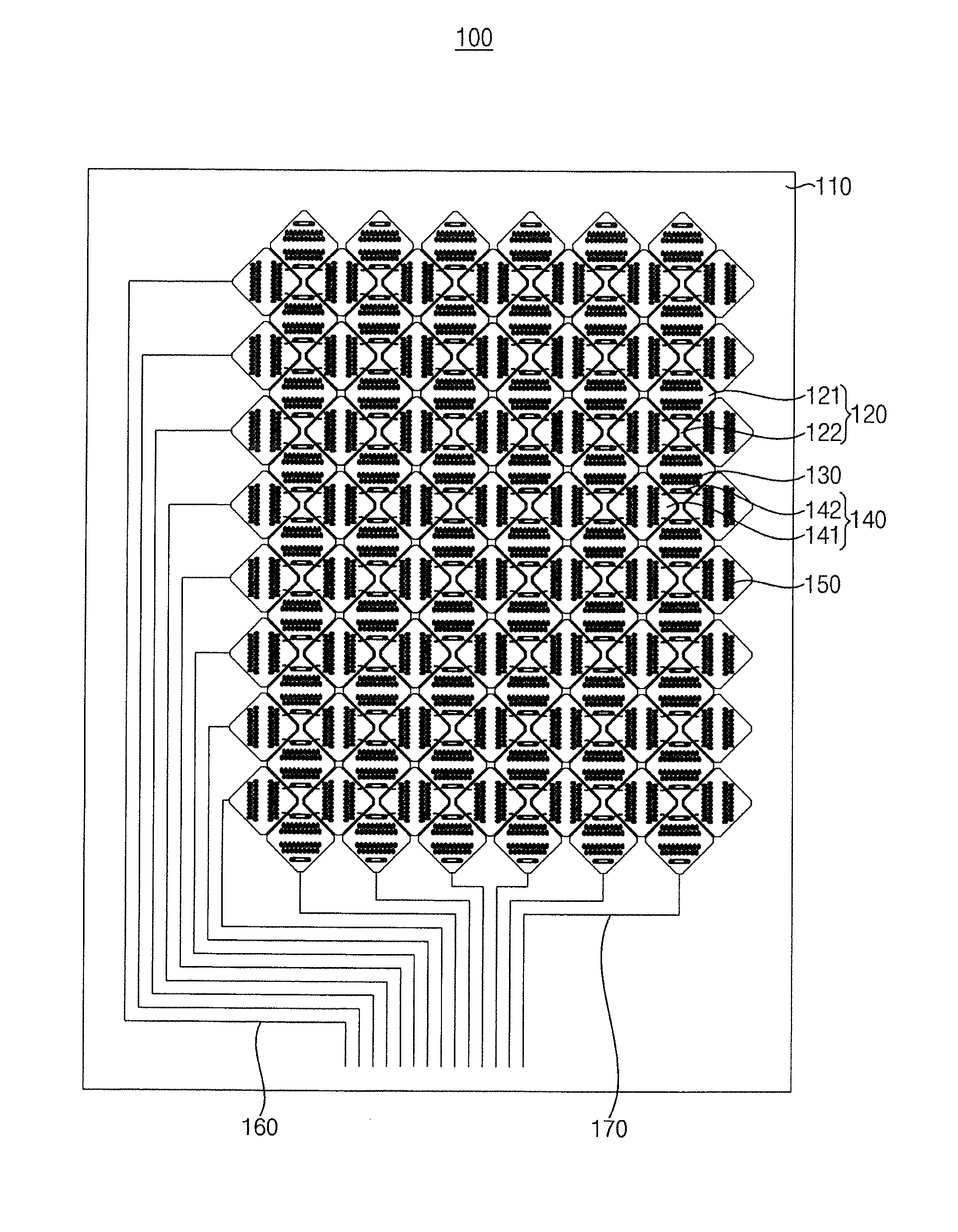
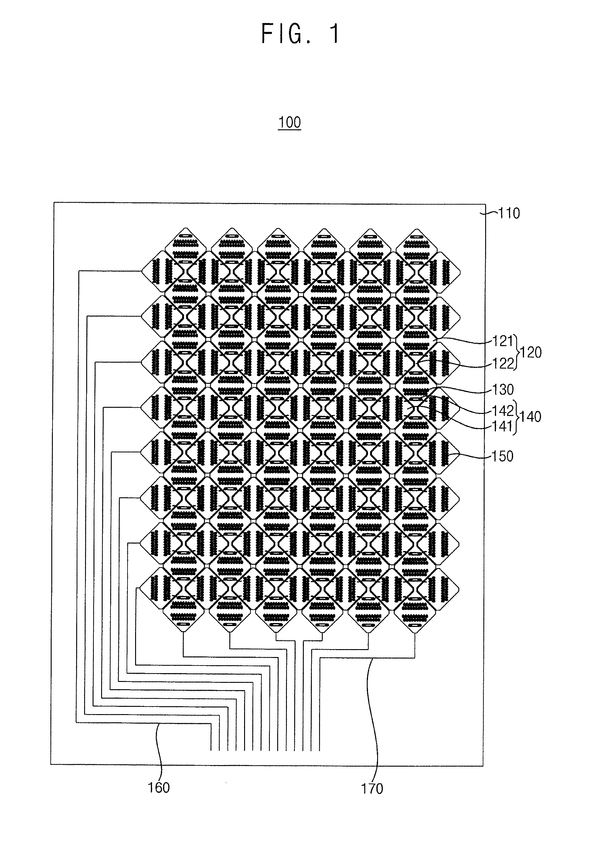
[0009]Example embodiments provide a touch screen panel that is capable of preventing failures of sensing and detecting operations by preventing or reducing damages to internal patterns through blocking or considerably reducing static electricity flowing into the touch screen panel.
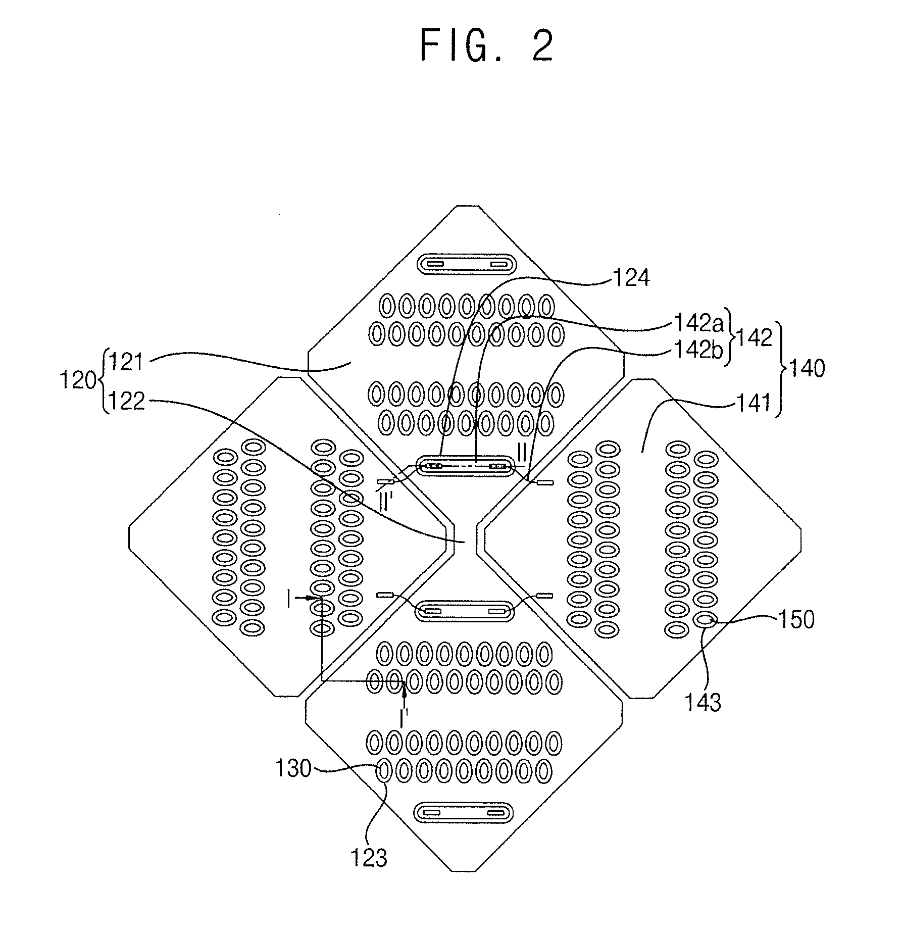
[0046]According to example embodiments, the first and the second sensing cells of the touch screen panel may include one or more openings provided adjacent to intersection portions between the first sensing lines and the second sensing lines, particularly the first and the second connection patterns. Additionally, conductive patterns may be respectively disposed in the openings. The static electricity flowed in the touch screen panel from the outside may be accumulated on the conductive patterns, so that the static electricity may be significantly reduced or removed. As a result, the damages to the components or the patterns of the touch screen panel may be effectively prevented to thereby improve the failures of touch operation of the touch screen panel.

Problems solved by technology

Thus, each of the first and the second connection patterns has a relatively large resistance, and an insulation layer located between adjacent connection patterns has a relatively small thickness because of limitation of deposition process and dimensions of the touch screen panel.
In a conventional touch screen panel having the above-described configuration, external static electricity may flow into the touch screen panel through the first and the second sensing lines such that the static electricity may cause serious damages to the first and the second connection patterns of the first and the second sensing lines.
If damages to the first and the second connection patterns are generated, the touch screen panel may not exactly detect and sense the touched position by the user.
Thus, the failure of operation may occur in the touch screen panel because of the damages to the first and the second sensing lines.

Method used


Image

  • Touch screen panels
  • Touch screen panels
  • Touch screen panels

Examples


Embodiment Construction

[0059]Various example embodiments will be described more fully hereinafter with reference to the accompanying drawings, in which some example embodiments are shown. The invention may, however, be embodied in many different forms and should not be construed as limited to the example embodiments set forth herein. Rather, these example embodiments are provided so that this description will be thorough and complete, and will fully convey the scope of the invention to those skilled in the art. In the drawings, the sizes and relative sizes of layers and regions may be exaggerated for clarity.

[0060]It will be understood that when an element or layer is referred to as being “on,”“connected to” or “coupled to” another element or layer, it can be directly on, connected or coupled to the other element or layer or intervening elements or layers may be present. In contrast, when an element is referred to as being “directly on,”“directly connected to” or “directly coupled to” another element or l...


PUM


Abstract

A touch screen panel includes a transparent substrate, a first sensing line and a second sensing line. The first sensing line includes first sensing cells arranged along a first direction and first connection patterns coupling the first sensing cells. The second sensing line includes second sensing cells arranged in a second direction substantially perpendicular to the first direction, and second connection patterns coupling the second sensing cells. At least one of the first and the second sensing cells includes openings and conductive patterns located in the openings.

Description

CROSS-REFERENCE TO RELATED APPLICATION[0001]This application claims priority under 35 USC §119 to and the benefit of Korean Patent Application No. 10-2012-0062874 filed on Jun. 12, 2012 in the Korean Intellectual Property Office (KIPO), the contents of which are herein incorporated by reference in their entirety.BACKGROUND[0002]1. Field[0003]Example embodiments of the present invention relate to touch screen panels.[0004]2. Description of the Related Art[0005]Recently, touch screen panels are widely being used for various display devices instead of input devices such as a remote control, a keyboard, a mouse, etc. The touch screen panel may be operated by touching information or icons thereon with a user's finger or a stylus pen. The touch screen panel may usually include a touching member for converting the position or the information selected by the user into an electrical signal, and then the touch screen panel may operate by the electrical signal.[0006]The touch screen panels may...

Claims


Application Information

Patent Timeline
Patent Type & Authority Applications(United States)
IPC IPC(8): G06F3/041
CPCG06F3/0418G06F3/0443G06F3/0446G06F3/0416G06F3/0448G06F3/044G06F2203/04111
Inventor HAN, KWAN-YOUNGJUNG, CHANG-SUBJEONG, HWAN-HEEKIM, SUNG-CHULCHOI, JAE-WOOKIM, TAE-IKPARK, HYUN-SIK
Owner SAMSUNG DISPLAY CO LTD
Why Eureka
Try Eureka