Light emitting module

Inactive Publication Date: 2013-12-12
LEXTAR ELECTRONICS CORP
View PDF5 Cites 6 Cited by
  • Summary
  • Abstract
  • Description
  • Claims
  • Application Information

AI Technical Summary

Benefits of technology

[0008]In view of the above, a technical aspect of the present invention provides a light emitting module in which light emi

Problems solved by technology

However, since in most of the current LED lamp panels, the LEDs are installed in a random distribution

Method used


Image

  • Light emitting module
  • Light emitting module

Examples


Embodiment Construction

[0014]Reference will now be made in detail to the present embodiments of the invention, examples of which are illustrated in the accompanying drawings. Wherever possible, the same reference numbers are used in the drawings and the description to refer to the same or like parts.

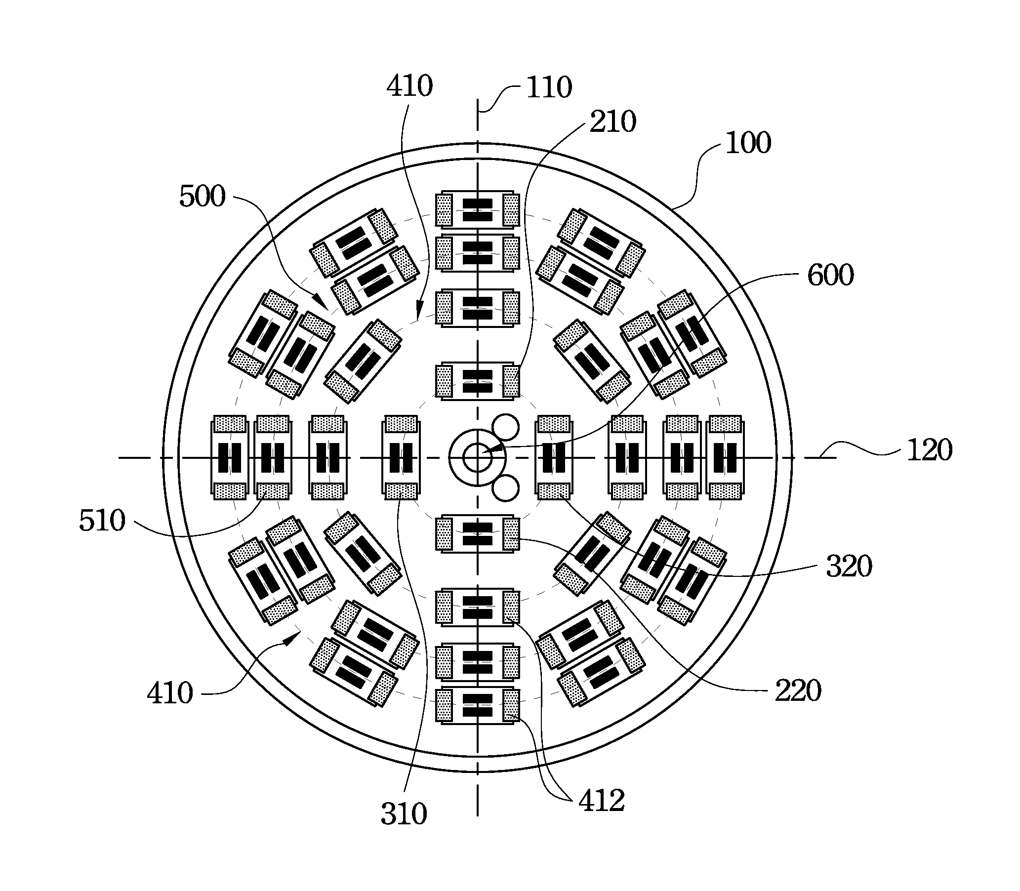
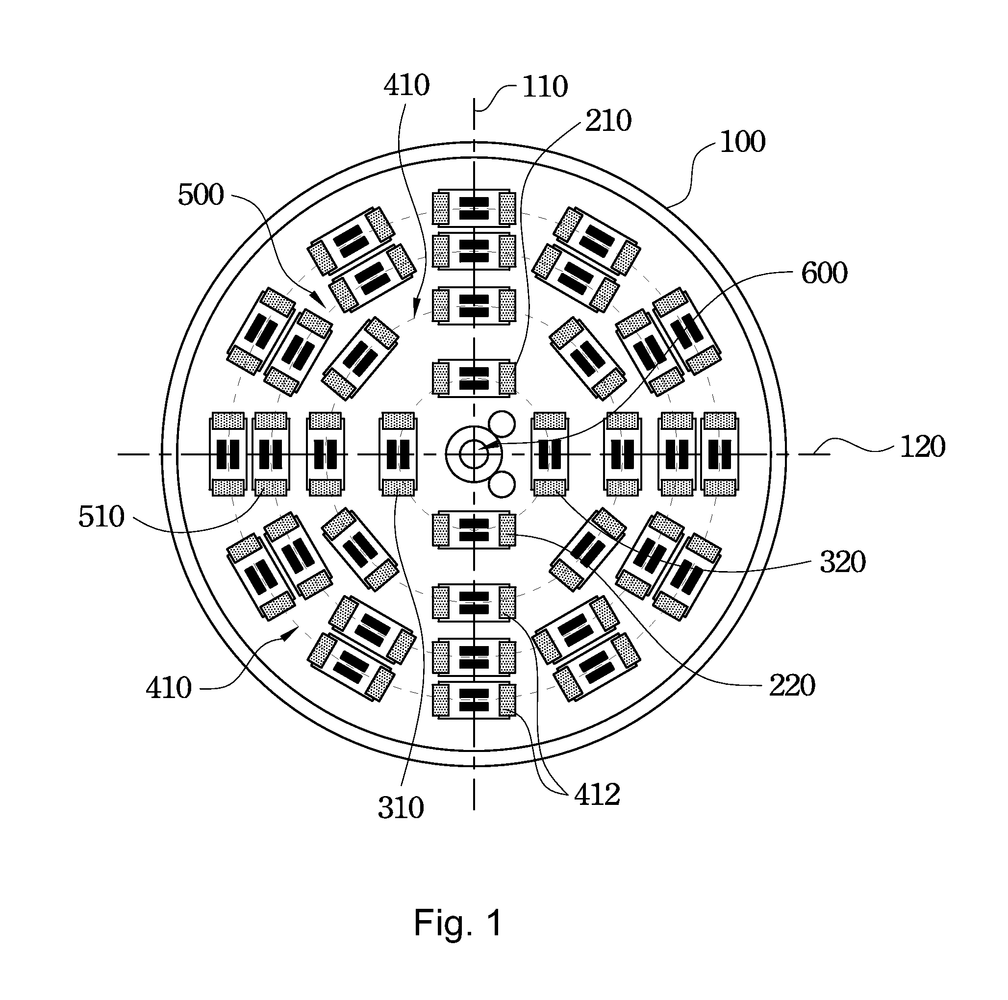
[0015]FIG. 1 is a top view of a light emitting module according to an embodiment of the present invention. As shown in the figure, the light emitting module according to this embodiment includes a substrate 100, two first LEDs (light emitting diode) 210 and 220, two second LEDs 310 and 320, and at least one first circular LED array 410. The substrate 100 has a first central line 110 and a second central line 120. The first central line 110 and the second central line 120 are substantially perpendicularly crossed on the center of the substrate 100. The first LEDs 210 and 220 are disposed oppositely on the first central line 110 of the substrate 100 and spatially separated by the center of the substrate 100. The...


PUM


Abstract

A light emitting module includes a substrate, two first LEDs (light emitting diode), two second LEDs (light emitting diode) and at least one first circular LED array. The substrate includes a first central line and a second central line. The first central line and the second central line are substantially perpendicularly crossed on the center of the substrate. The first LEDs are disposed oppositely on the first central line and spatially separated by the center of the substrate. The second LEDs are disposed oppositely on the second central line and spatially separated by the center of the substrate. The color temperature of the light emitted by the first LEDs is different from which by the second LEDs. The first circular LED array is disposed on the substrate.

Description

RELATED APPLICATIONS[0001]This application claims priority to Taiwan Application Serial Number 101211003, filed Jun. 7, 2012, which is herein incorporated by reference.BACKGROUND[0002]1. Technical Field[0003]Embodiments of the present invention relate to a light emitting module, and more particularly relate to a light emitting module employing a light emitting diode.[0004]2. Description of Related Art[0005]In recent years, with the rising of environmental awareness, eco-friendly product has become the main trend in industry development. In order to achieve the purpose of the eco-friendly trend, a conventional tungsten lamp is replaced by a light emitting diode (LED) with low power consumption and high efficiency.[0006]Currently, common LED lamps mainly include a LED lamp panel. For the LED lamp panel, a plurality of LED packages are arranged on a circuit substrate to emit light.[0007]However, since in most of the current LED lamp panels, the LEDs are installed in a random distributi...

Claims


Application Information

Patent Timeline
IPC IPC(8): F21V14/00
CPCF21V14/00F21K9/60F21Y2105/10F21Y2105/12
Inventor LIN, YU-LING
Owner LEXTAR ELECTRONICS CORP
Why Eureka
Try Eureka