Emergency alert system

Inactive Publication Date: 2013-12-12
HELP NOW TECH
View PDF11 Cites 121 Cited by
  • Summary
  • Abstract
  • Description
  • Claims
  • Application Information

AI Technical Summary

Benefits of technology

[0006]The various aspects of the present invention provide a system, device, and/or method that allows simple, fast, and automatic communication with an emergency services operator. The device may be worn by a user and, upon activation, all desired emergency communications are subsequently made without further user intervention. This ensures that communication with the emergency services operator will take place even if the person activating the device later becomes incapacit

Problems solved by technology

In other embodiments, the alert device may lack any contr

Method used


Image

  • Emergency alert system
  • Emergency alert system
  • Emergency alert system

Examples


first embodiment

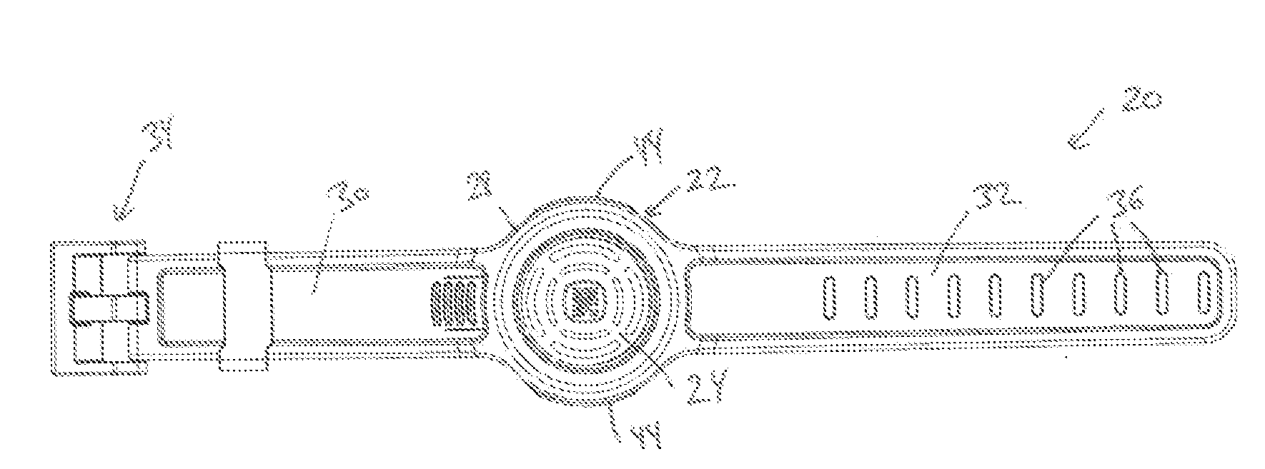
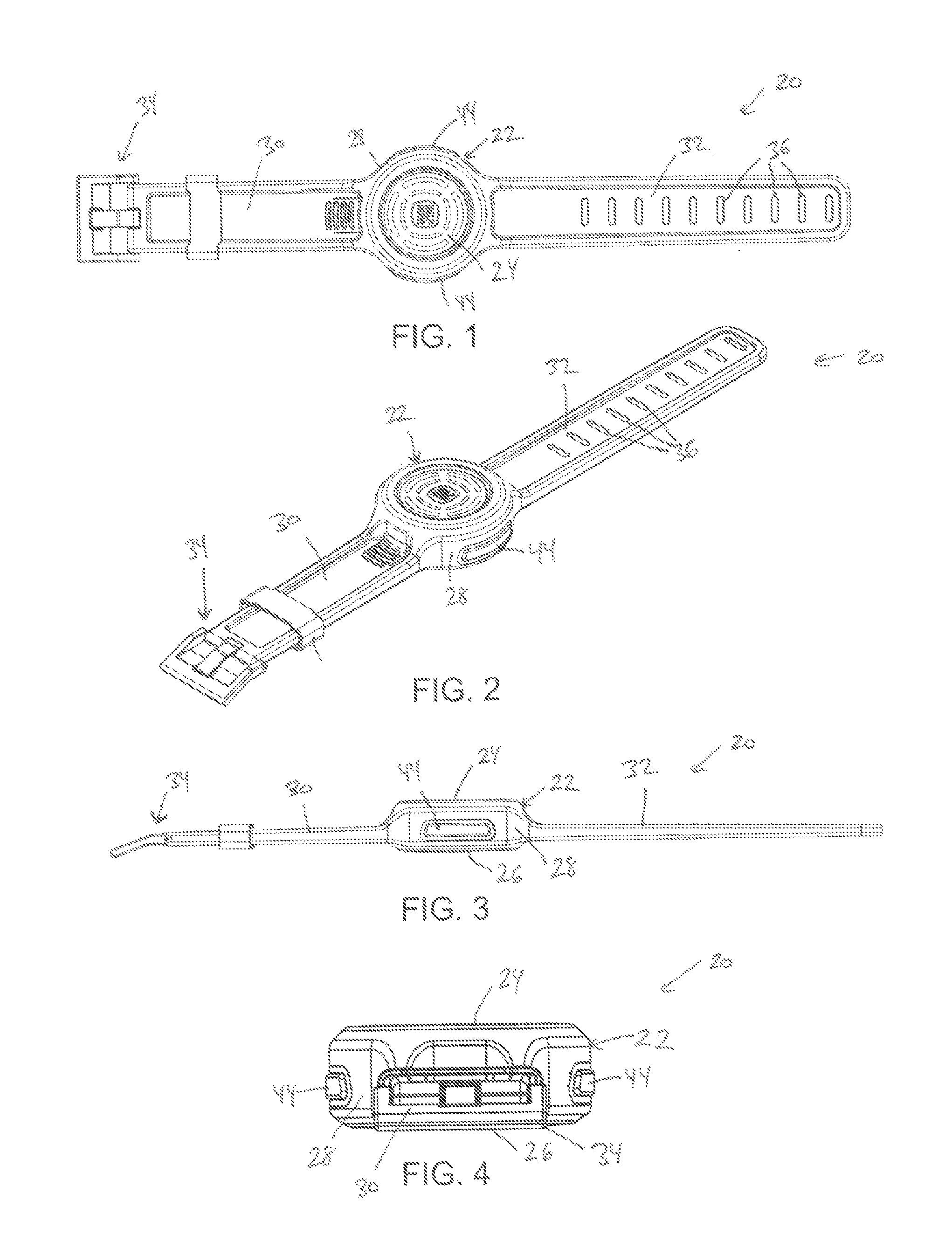
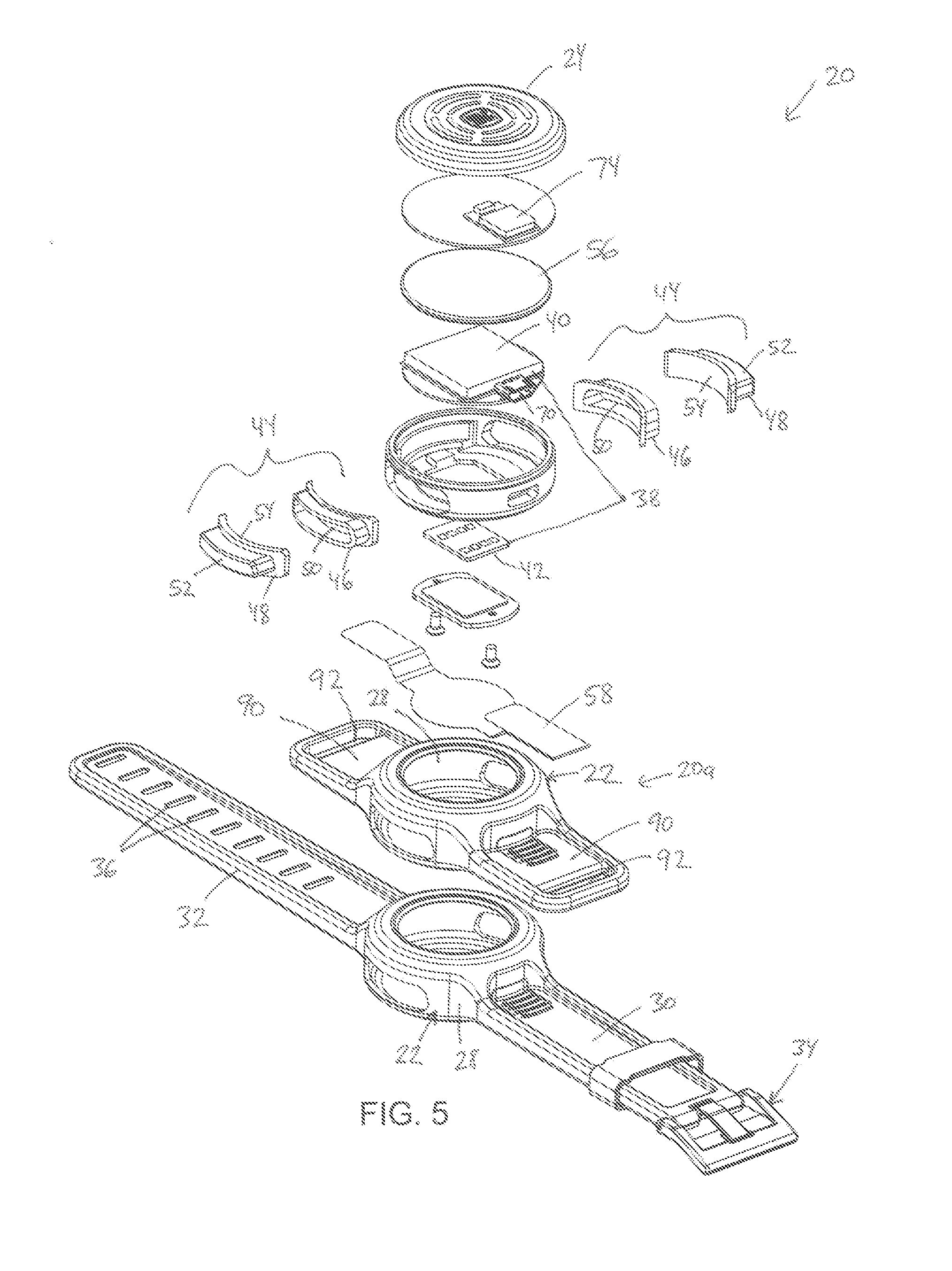
[0043]A wearable emergency alert device 20 is shown in FIG. 1. Alert device 20 includes a generally cylindrical or disk shaped housing 22 having a top face 24, a bottom face 26, and a perimeter wall 28. A first band 30 is coupled to, or integrated into, housing 22 along a first side, while a second band 32 is coupled to, or integrated into, housing 22 along a second side that is opposite to the first side. First and second bands 30 and 32 are adapted to allow wearable alert device 20 to be releasably attached to a person's wrist. To that end, first band 30 may include a buckle 34 attached at an end opposite housing 22, while second band 32 may include a series of holes or apertures 36 to which the prong of buckle 34 may be selectively inserted in order to secure device 20 to wrists of varying diameter. It will be understood that the combination of buckle 34 and apertures 36 could be replaced by other fastening systems for enabling device 20 to be worn on a user's wrist, such as, bu...

third embodiment

[0078]FIGS. 11-14 illustrate device 20b. As with the embodiments of FIGS. 1-5 and 6-10, device 20b of FIGS. 11-14 may include the same internal components as device 20 of FIGS. 1-5, and may operate in accordance with algorithm 60, or variations thereof, or in accordance with one or more different algorithms. Device 20b of FIGS. 11-14 includes a housing 22 having a top face 24, a bottom face 26, and a perimeter wall 28. Integrated into a portion of perimeter wall 28 are a pair of sliding doors 96. Sliding doors 96 may be coupled to one or biasing members (not shown), such as springs, or the like, that urge sliding doors 96 toward the closed position illustrated in FIG. 11. When a user applies sufficient force to doors 96, the user urges them apart and into the position shown in FIG. 12. When the doors 96 are urged apart, a user has access to one or more buttons 98. Buttons 98 act in the same manner as tactile switches 44 described above, or they may control device 20b in other manner...

fourth embodiment

[0080]FIGS. 15-18 illustrate a wearable emergency alert device 20c. In this embodiment, wearable emergency alert device 20c is integrated into a conventional wrist watch 102. Specifically, alert device 20c is attached to a back face of the wrist watch. The device 20c therefore does not need any separate bands to couple it to wrist watch 102. While the embodiment shown in FIGS. 15-18 shows device 20c as being a generally separate component of wrist watch 102, it will be understood by those skilled in the art that device 20c could be contained within a common housing that housed both the timekeeping components of wrist watch 102 as well as controller 38 and its associated components. Indeed, in some embodiments, device 20c could share one or more components with wrist watch 102, including, but not limited to, a battery, a microcontroller, or other control circuitry, and / or user interface structures (e.g. buttons, controls, etc.).

[0081]As shown in FIGS. 15-18, device 20c includes a pai...


PUM


Abstract

An emergency alert device is adapted to be worn by a user and to automatically make a cellular phone call to an emergency services center upon activation by a user. The device automatically transmits its current location—derived from GPS, cellular telephone triangulation, or otherwise—via text message, if the emergency services center is equipped to receive text messages, or via a synthesized voice if the emergency services center is not so equipped. The user does not need to dial any phone numbers to activate the call. The device may be attached to, or incorporated into, a wrist watch. A text message is also automatically sent to a recipient who is pre-designated by the user. The text message includes the current location of the user. Repeated text messages are sent if the user's position changes by more than a threshold.

Description

CROSS-REFERENCE TO RELATED APPLICATIONS[0001]This application claims priority to U.S. patent application Ser. No. 61 / 658,526 filed Jun. 12, 2012 by applicant Rebecca S. Harvey, entitled EMERGENCY ALERT SYSTEM, the complete disclosure of which is hereby incorporated herein by reference.BACKGROUND OF THE INVENTION[0002]The present invention relates to emergency alerting systems and / or devices that may be used to contact emergency services operators and / or other people in the case of an emergency.[0003]In the event of a medical emergency, a security emergency, or any other type of emergency in which assistance is required, a person may wish to summon assistance by calling 911, or by dialing other digits that place the person needing help in communication with an emergency service operator. In some situations, however, the person needing assistance may not be able to make a conventional phone call. For example, the person may be suffering from a health emergency that makes it difficult ...

Claims


Application Information

Patent Timeline
IPC IPC(8): H04W4/22H04W4/90
CPCH04W4/22H04W4/90
Inventor HARVEY, REBECCA S.
Owner HELP NOW TECH
Why Eureka
Try Eureka