Method And Apparatus For Coordinated Beamforming

a beamforming and beam technology, applied in the field of communication, can solve the problems of random and unpredictable hotspot area in the public safety network, inability to meet the needs of high data rate applications, and inability to directly apply commercial lte technologies to the public safety network

Inactive Publication Date: 2013-12-12
ALCATEL LUCENT SAS
View PDF6 Cites 63 Cited by
  • Summary
  • Abstract
  • Description
  • Claims
  • Application Information

AI Technical Summary

Benefits of technology

[0018]Another network equipment apparatus is also provided. This network equipment is configured to communicate with other equipment in a communication system and is operative to detect a wireless denial of service (WDoS) attack from a first wireless node and to direct a signaling beam toward the first wireless node to suppress signaling from the first wireless node. While suppressing signaling from the first wireless node, the network equipment is operative to provide service to other wireless nodes.

Problems solved by technology

In addition, the hotspot area in the public safety network is random and unpredictable, which is different from the traditional WiFi systems.
However, the narrow band systems are not suitable for high data rate applications, such as multimedia streaming.
Thus, the direct application of commercial LTE technologies may not be the best solution for the public safety network [4].

Method used


Image

  • Method And Apparatus For Coordinated Beamforming
  • Method And Apparatus For Coordinated Beamforming
  • Method And Apparatus For Coordinated Beamforming

Examples


Embodiment Construction

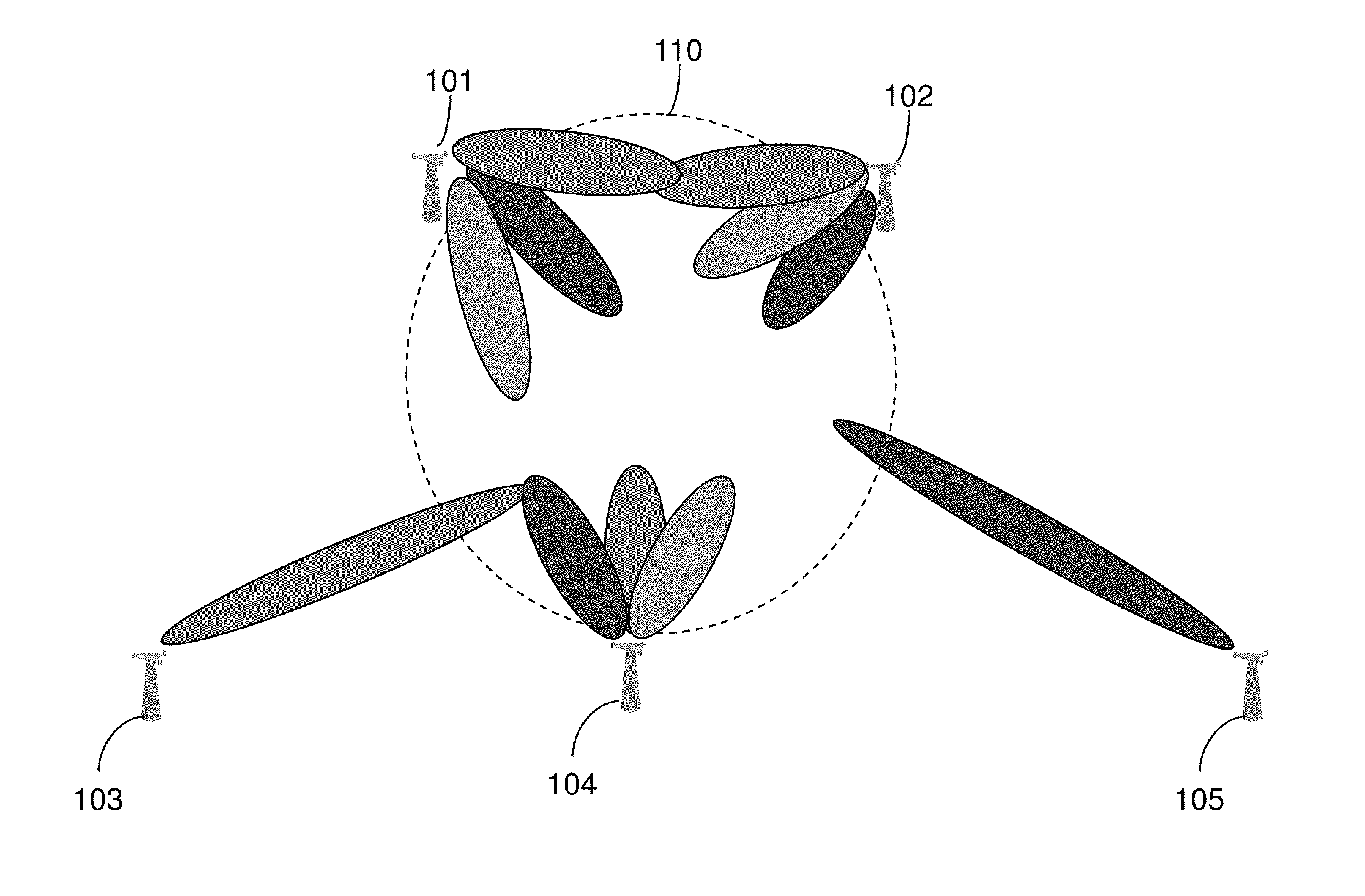
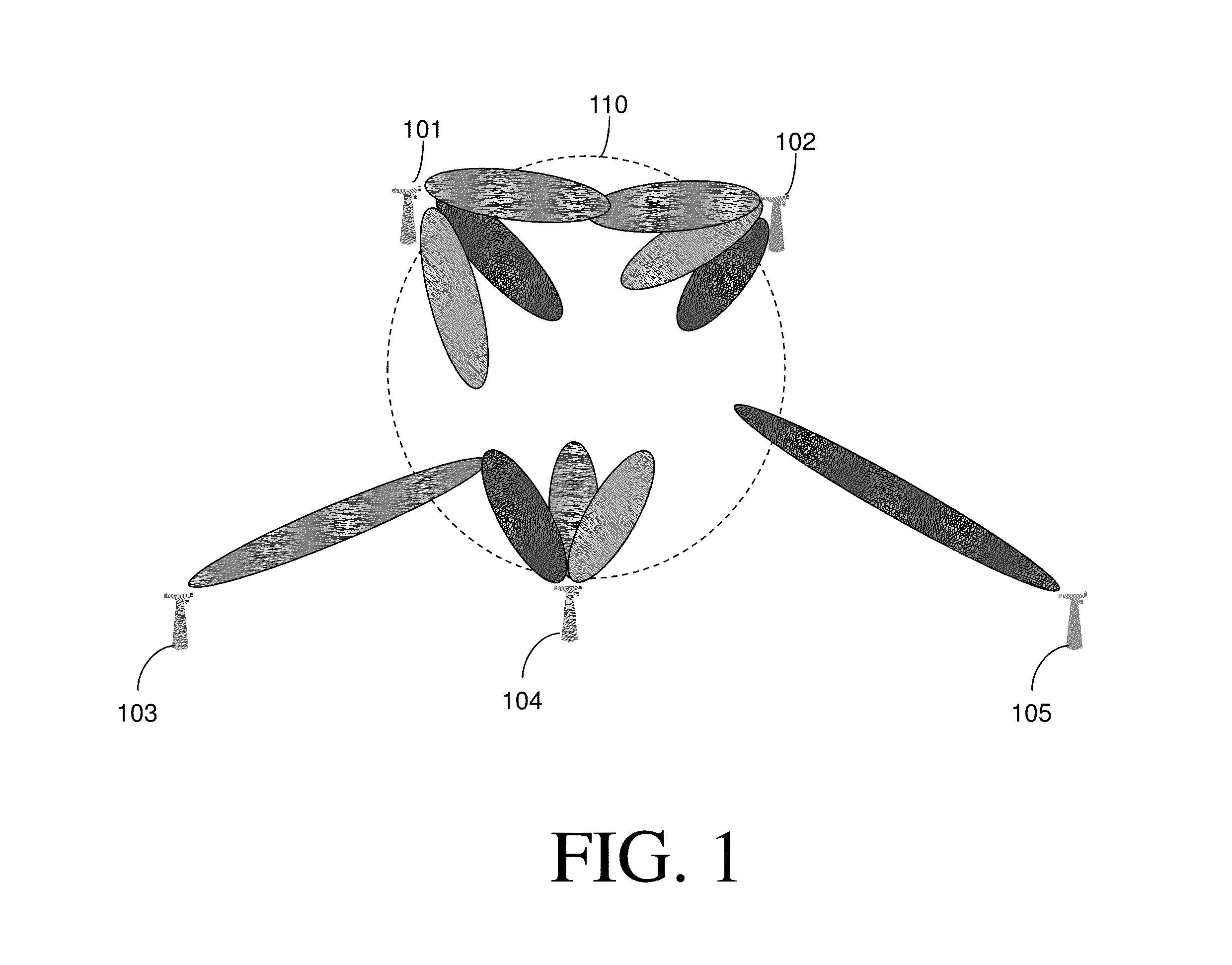
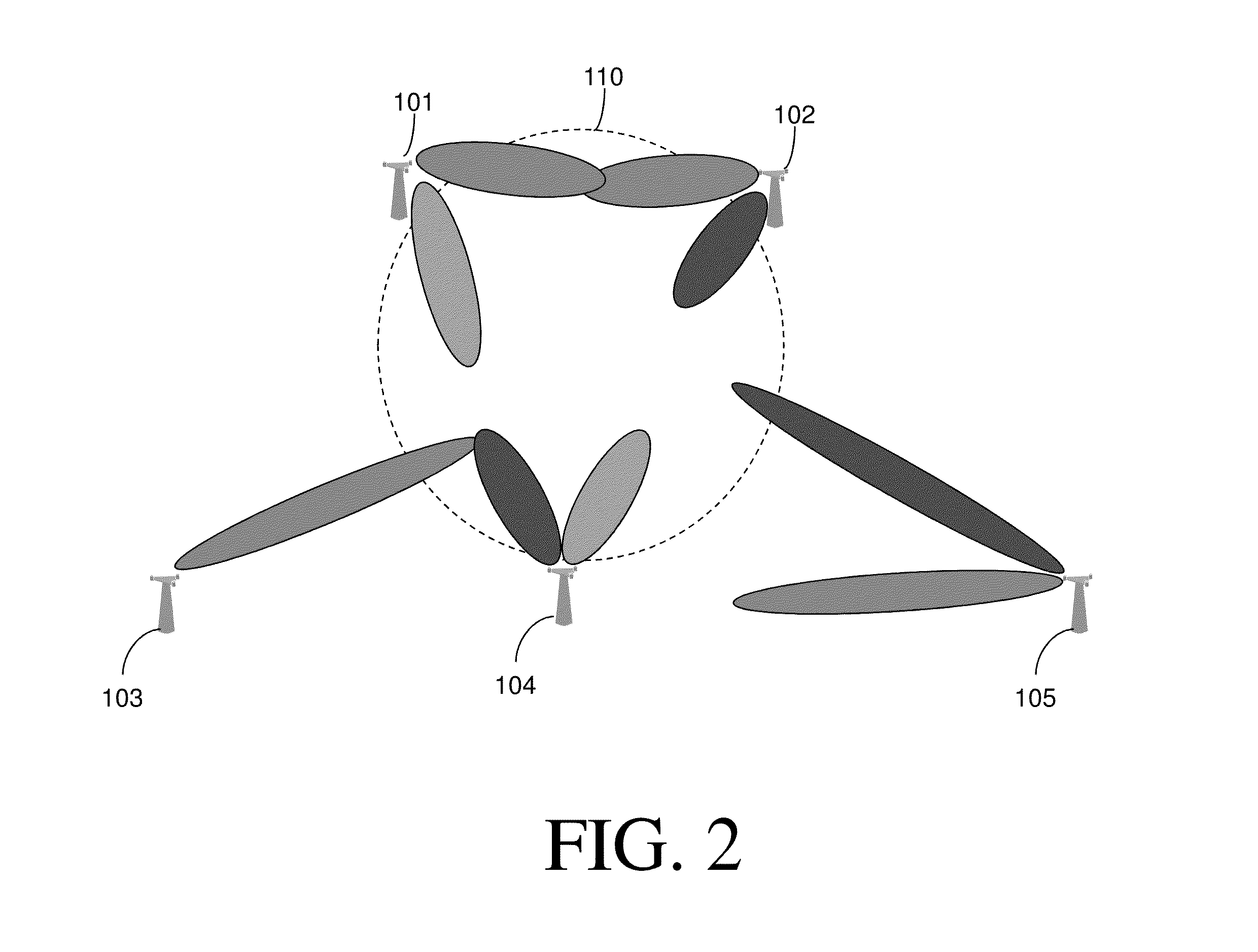
[0019]To provide a greater degree of detail in making and using various aspects of the present invention, a description of our approach to communications in public safety networks and a description of certain, quite specific, embodiments follows for the sake of example. FIGS. 1-3 are referenced in an attempt to illustrate some examples of specific embodiments of the present invention.

[0020]To cope with the aforementioned challenges, we propose a coordinated dual-layer beamforming (CoB) system for highly reliable and spectrum-efficient communications in public safety networks. We assume each BS is equipped with a beamforming antenna that is capable of choosing one or multiple beams from a set of pre-computed beamforming patterns according to the traffic condition. Such an approach could significantly enhance the system throughput and thereby increase the number of UEs that can be simultaneously connected. For example, as shown in FIGS. 1 and 2, whenever a fire emergency occurs in a s...


PUM


Abstract

Various methods and devices are provided to improve wireless communications. In one method, a need for additional wireless service in a target area is detected (401). As part of a first-layer beamforming process, a signaling beam is directed (402) toward the target area. As part of a second-layer beamforming process, at least some inter-cell interference is canceled (403) in the target area. In another method, a wireless denial of service (WDoS) attack from a first wireless node is detected (501). A signaling beam is directed (502) toward the first wireless node to suppress signaling from the first wireless node. While suppressing this signaling, service is provided (503) to other wireless nodes.

Description

REFERENCE(S) TO RELATED APPLICATION(S)[0001]The present application claims priority from a provisional application Ser. No. 61 / 656,789, entitled “METHOD AND APPARATUS FOR COORDINATED BEAMFORMING,” filed Jun. 7, 2012, which is commonly owned and incorporated herein by reference in its entirety.FIELD OF THE INVENTION[0002]The present invention relates generally to communications and, in particular, to beamforming in wireless communication systems.BACKGROUND OF THE INVENTION[0003]This section introduces aspects that may help facilitate a better understanding of the inventions. Accordingly, the statements of this section are to be read in this light and are not to be understood as admissions about what is prior art or what is not prior art.[0004]Commercial wireless networks are designed to either provide ubiquitous mobile access across a large geographical area, for example, the 3G and 4G metro cellular networks or a hotspot area with dense users (such as the indoor systems, e.g. Femto,...

Claims


Application Information

Patent Timeline
Patent Type & Authority Applications(United States)
IPC IPC(8): H04B15/00G06F21/00
CPCH04B7/024H04B7/0617H04B7/0619H04W16/28H04W72/046H04W76/50H04W72/27
Inventor YANG, KAICALIN, DORUKAYA, ALIYE OZGEYIU, SIMON
Owner ALCATEL LUCENT SAS
Why Eureka
Try Eureka