
Apparatus, systems, and methods for performing laparoscopic surgery

Active Publication Date: 2013-12-12
THE BOARD OF TRUSTEES OF THE LELAND STANFORD JUNIOR UNIV
View PDF2 Cites 25 Cited by
  • Summary
  • Abstract
  • Description
  • Claims
  • Application Information

AI Technical Summary

Benefits of technology

The present invention is about surgical tools and systems for laparoscopic surgery that minimize access sites and screws. A modular tool head is provided that can be connected to a surgical tool for use in a patient's body. The tool head has a housing, end effector elements, and an actuator link for directing the end effector between open and closed positions. A locking element can prevent the actuator link from moving substantially. These tools and systems help surgeons to perform surgeries with reduced tissue damage and improved outcomes.

Problems solved by technology

However, the size of the tool tips on conventional instruments used in laparoscopic procedures generally limit the ability to reduce the size of the incisions and trocars needed for such procedures.
This results in hidden scar post operatively.
However, manipulation is more challenging because the tight aperture of the belly button and strong connective tissue in the abdominal wall forces all the instruments to move dependent on one another.
In addition, the surgeon's hands are crowded together because of these constraints.
This makes the procedure frustrating to perform compared to other approaches.
However, constraints of the belly button port may force these articulating tools to cross, thus reversing the left-right motion between what the surgeon does with his hands and what he sees on the video monitor.
Also, the complex mechanics behind the articulation may drive the cost up significantly.
But, the number of trocar ports used in an operation is trauma-limited.
Surgeons often hesitate to place more ports, even if it would mean making the procedure easier to do, because of the increased risk of wound complications with each additional incision (such as infection, dehiscence, or hernia).

Method used


Image

  • Apparatus, systems, and methods for performing laparoscopic surgery
  • Apparatus, systems, and methods for performing laparoscopic surgery
  • Apparatus, systems, and methods for performing laparoscopic surgery

Examples


Embodiment Construction

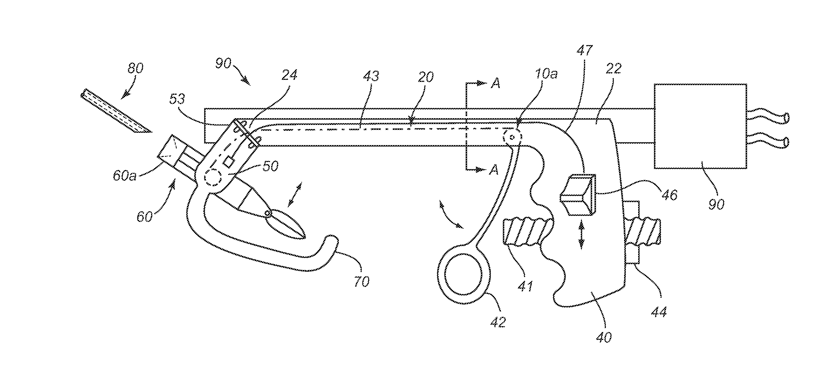
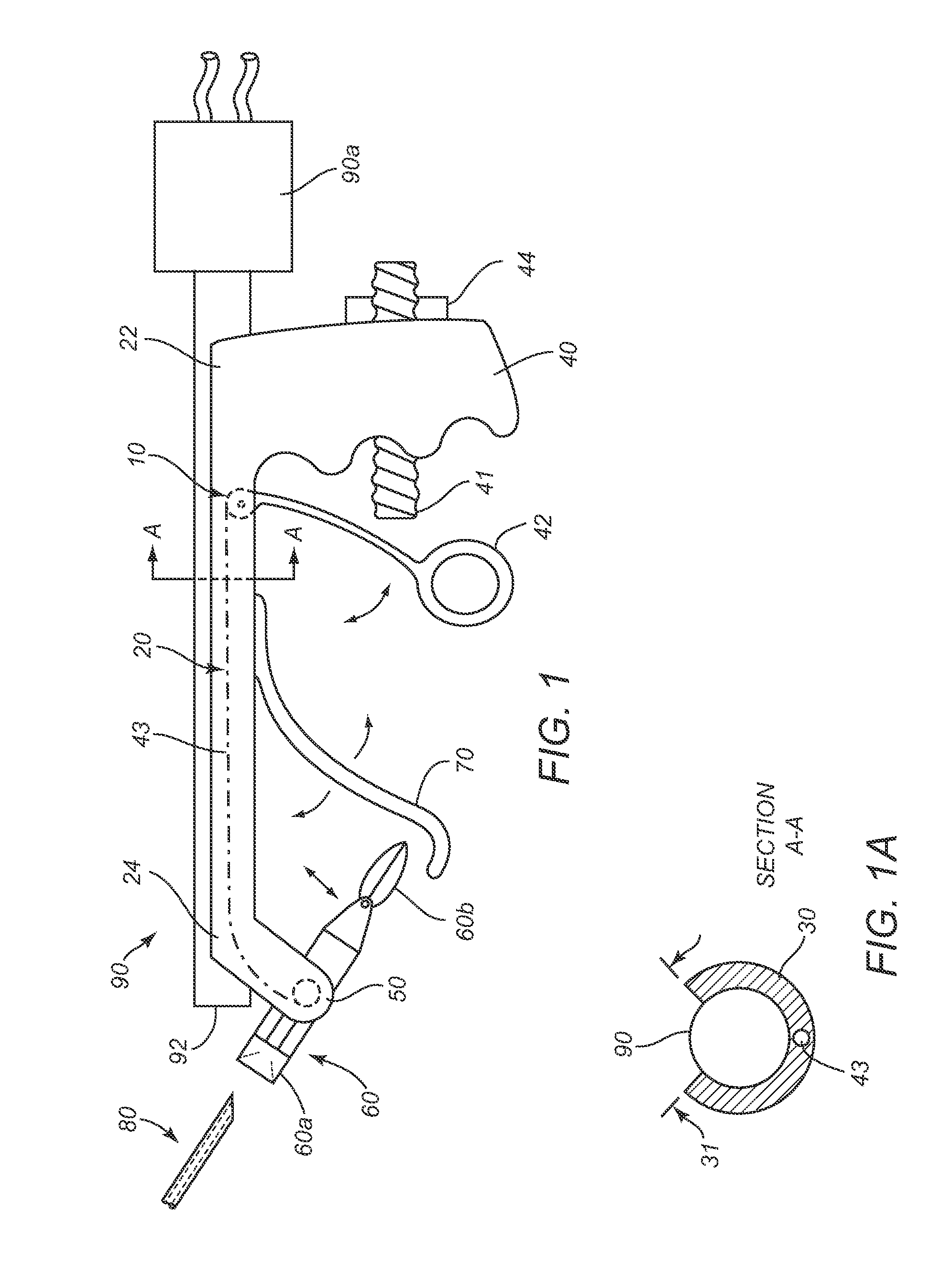
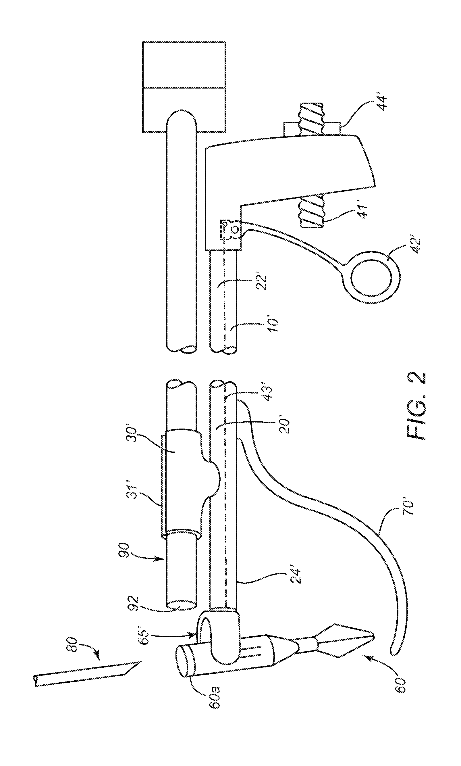
[0095]Turning to the drawings, FIG. 1 shows an exemplary embodiment of an introduction apparatus 10 that includes an elongate shaft 20 including a proximal end 22 and a distal end 24, one or more clip elements 30 for slidably securing the shaft 20 to an endoscope 90, a handle 40 on the proximal end 22, and a housing 50 on the distal end 24 for releasably engaging a tool head 60. The handle 40 may include a trigger or other actuator 42, e.g., for operating the housing 50 to engage and / or release a tool head 60 with a connecting or actuating wire or rod 43.

[0096]As best seen in FIG. 1A, the shaft 20 includes a generally “U” or “C” shaped cross-section, e.g., having a periphery greater than one hundred eighty degrees (180°), thereby defining opposing clip elements 30 for securing the shaft 20 to the housing 50. The shaft 20 and / or clip elements 30 may be formed from substantially rigid or semi-rigid material, e.g., plastic, metal, or composite materials, having sufficient rigidity to m...


PUM


Abstract

Apparatus, systems, and methods for laparoscopic abdominal surgery are disclosed. For example, a system or kit is provided for performing a procedure within a surgical space within a patient's body that includes a plurality of tool heads, and a tool head carrier including features for removably receiving one or more tool heads, the tool head carrier sized for introduction through a trocar or other port into a surgical space. The system or kit may also include a surgical tool including a tool shaft introduceable into the surgical space and including features for securing a tool head to the tool. Optionally, the tool head carrier may include a clip for securing the tool head carrier to an endoscope.

Description

[0001]RELATED APPLICATION DATA[0002]This application is a continuation of co-pending International Application No. PCT / US2012 / 025136, filed Feb. 14, 2012, which claims benefit of U.S. provisional application Ser. No. 61 / 442,788, filed Feb. 14, 2011, the entire disclosures of which are expressly incorporated by reference herein. This application is also related to U.S. provisional application Ser. No. 61 / 314,595, filed Mar. 17, 2010, and international application no. PCT / US2010 / 001036, filed Apr. 5, 2010, published as International Publication No. WO 2010 / 114634, the entire disclosures of which are expressly incorporated by reference herein.FIELD OF THE INVENTION[0003]The present invention relates generally to apparatus, systems, and methods for performing surgery, e.g., laparoscopic surgery, and more particularly, to laparoscopic surgical tools and to systems and methods including such tools.BACKGROUND[0004]Surgery has become increasingly less invasive thanks to advances in medical ...

Claims


Application Information

Patent Timeline
IPC IPC(8): A61B1/313A61B17/29
CPCA61B1/3132A61B17/29A61B2017/00265A61B2017/00362A61B2017/00455A61B2017/292A61B2017/2927A61B2017/2929A61B2017/2931A61B2017/2936A61B2017/00473A61B2017/2946A61B2090/031A61B2090/08021A61B2090/0808A61B2090/0811
Inventor PELL, CHRISTOPHER STEVENDUGGAN, BRYAN J.DONG, HATTIE ZHI CHENRUBY, THOMASROOP, JOHN AVITICKER, JONATHAN B.LAU, JAMES N.CHAO, KEVIN
Owner THE BOARD OF TRUSTEES OF THE LELAND STANFORD JUNIOR UNIV
Learn More