Cutting tool
a cutting tool and cutting technology, applied in the field of cutting tools, can solve the problems of increasing the wind noise and vibration of the motor itself, and achieve the effect of reducing the noise and vibration of the cutting tool, and reducing the wind noise or vibration mainly
- Summary
- Abstract
- Description
- Claims
- Application Information
AI Technical Summary
Benefits of technology
Problems solved by technology
Method used
Image
Examples
first embodiment
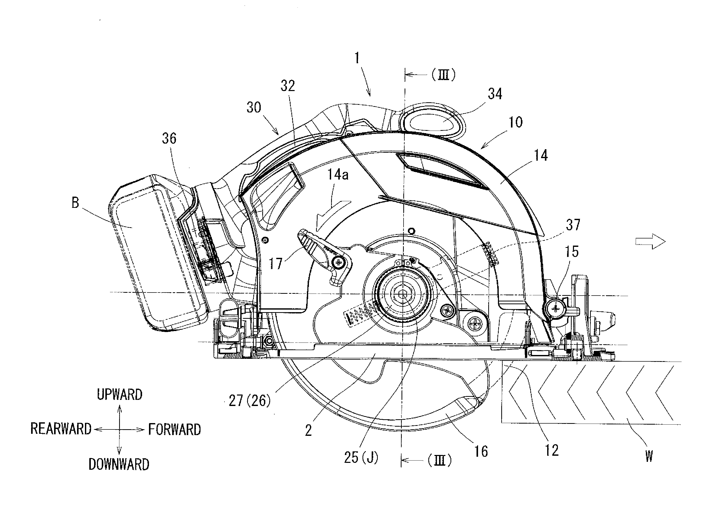
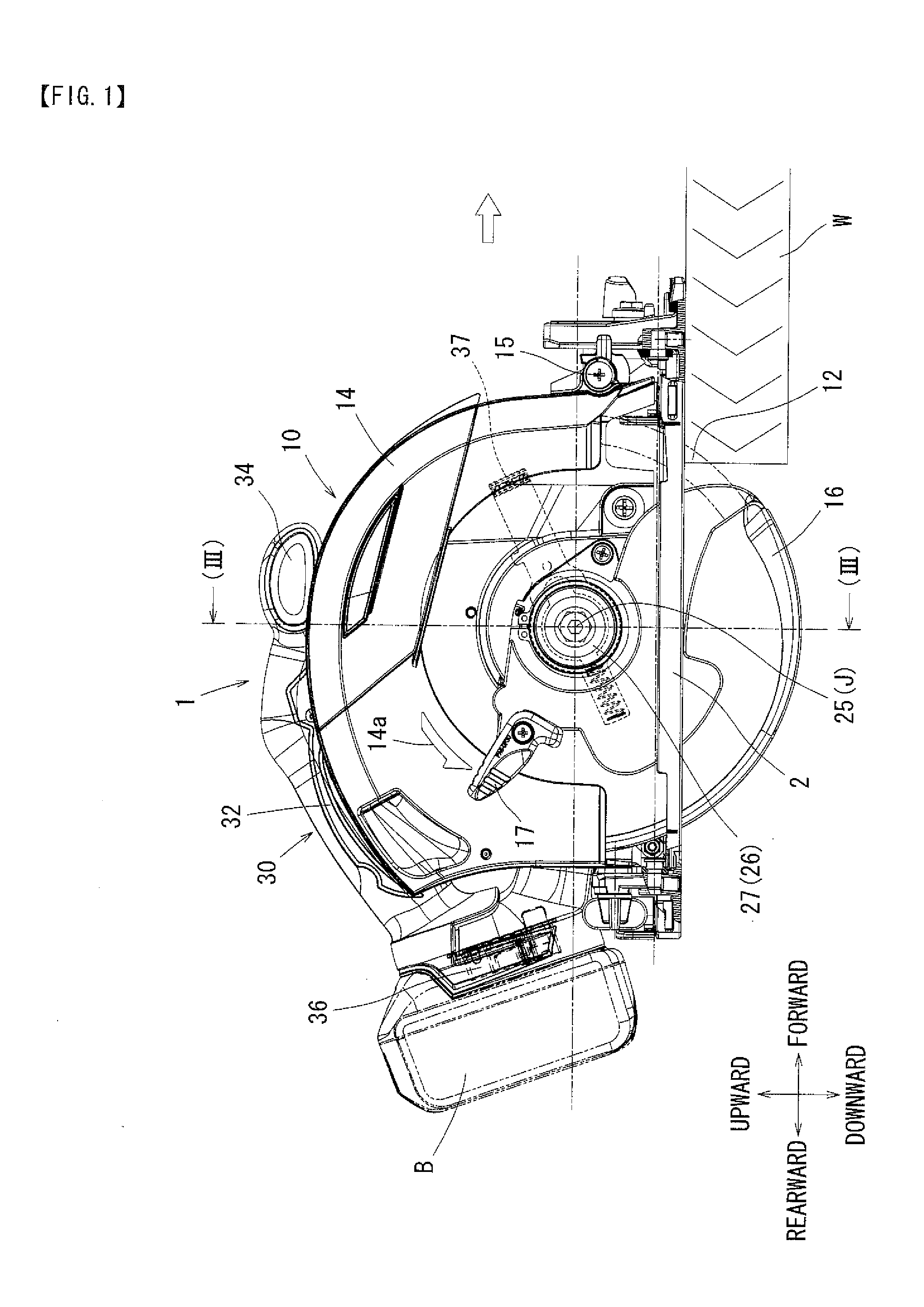
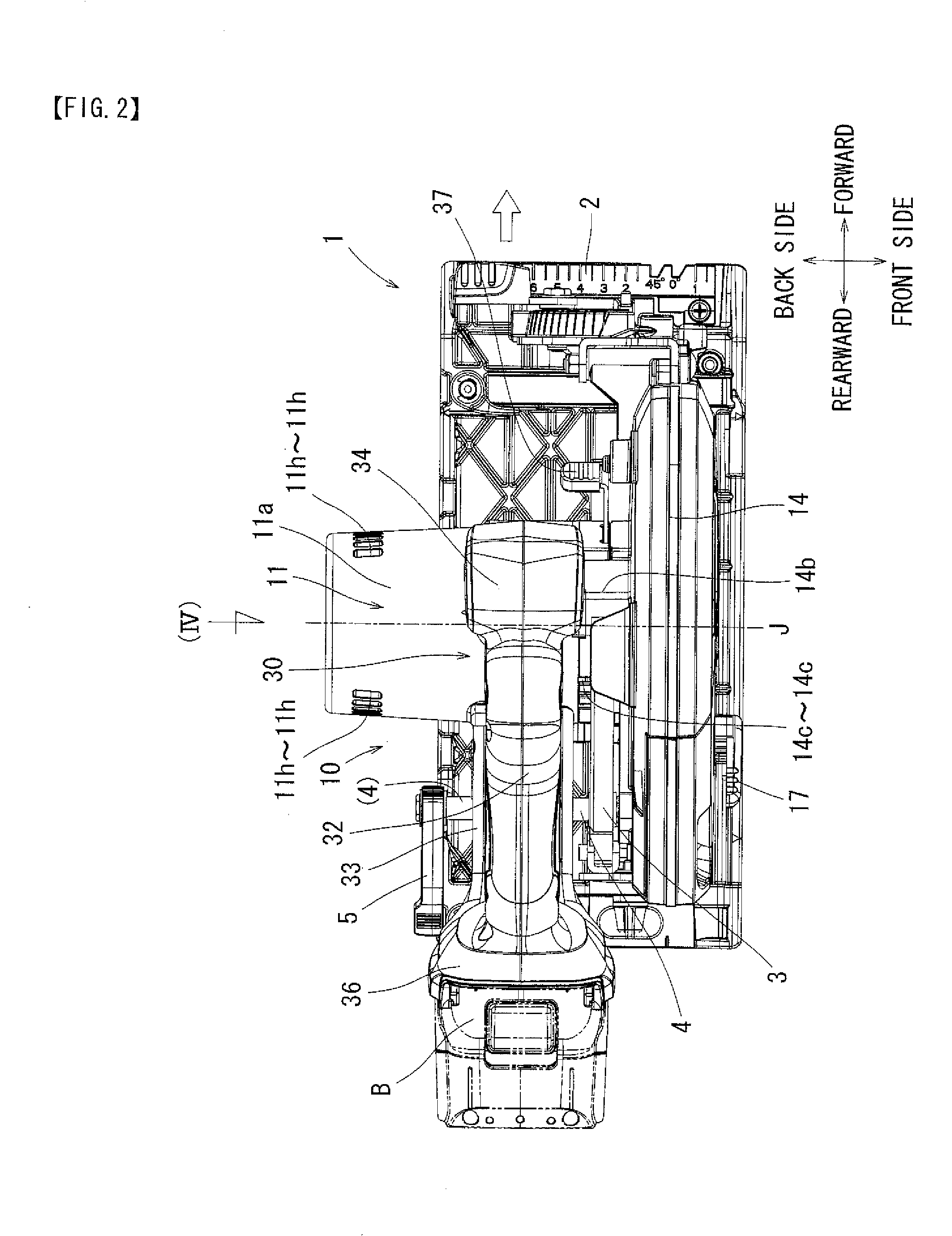
[0105]The first embodiment described above may be modified in various ways. For example, the above embodiment incorporates the direct drive system (the ratio α=1.0), in which the rotary cutter 12 is directly mounted to the output shaft 11d of the electric motor 11, whereby the outer rotor type electric motor 11 as the drive source is rotated at a low speed rotation for achieving a reduction in noise and vibration of the cutting tool 1. However, it is possible to attain the same effect by setting the rotational output of the electric motor 11 to a range of the ratio α=0.5 to 2.0 through the intermediation of a shaft displacement mechanism 20 that will be described below.
[0106]FIG. 5 shows a cutting tool 50 according to the second embodiment. The components and the construction that are the same as those of the first embodiment are labeled with the same reference numerals, and a description thereof will be omitted. in the case of the second embodiment, the shaft displacement mechanism...
second embodiment
[0109]With the cutting tool 50 constructed as described above, the rotational output of the electric motor 11 is transmitted to the rotary cutter 12 via the shaft displacement mechanism 20 whose ratio α is set to 1.0. Thus, if the proper rotational speed Re of the rotary cutter 12 is, for example, approximately 6,000 RPM, it is possible to also set the rotational speed Rm of the electric motor 11 to approximately 6,000 RPM.
[0110]Conventionally, when using an electric motor as the drive source of an electric tool, it is normally rotated at a high speed of approximately 25,000 RPM; in this regard, according to the second embodiment, it is enough to rotate the outer rotor type electric motor 11 at a very low-speed of approximately 6,000 RPM, so that it is possible to achieve a reduction in the wind noise and vibration of mainly the cooling fan 11e of the electric motor 11 and eventually to realize a reduction in the noise and vibration of the cutting tool 50.
[0111]The exemplified rati...
third embodiment
[0115]Also in this third embodiment, the rotational output of the electric motor 11 is transmitted to the rotary cutter 12 via the shaft displacement mechanism 40 whose ratio α is set to 1.0. Thus, if the proper rotational speed Re of the rotary cutter 12 is, for example, approximately 6,000, it is also possible to set the rotational speed Rm of the electric motor 11 to approximately 6,000.
[0116]Conventionally, when using an electric motor as the drive source of an electric tool, it is normally rotated at a high speed of approximately 25,000 RPM; in this regard, according to the third embodiment, it is enough to rotate the outer rotor type electric motor 11 at a very low-speed of approximately 6,000 RPM, so that it is possible to achieve a reduction in the wind noise and vibration of mainly the cooling fan 11e of the electric motor 11 and eventually to realize a reduction in the noise and vibration of the cutting tool 60.
[0117]Also in the third embodiment, the exemplified ratio α ma...
PUM
| Property | Measurement | Unit |
|---|---|---|
| diameter | aaaaa | aaaaa |
| diameter | aaaaa | aaaaa |
| distance L1 | aaaaa | aaaaa |
Abstract
Description
Claims
Application Information
 - R&D
- Intellectual Property
- Life Sciences
- Materials
- Tech Scout
- Unparalleled Data Quality
- Higher Quality Content
- 60% Fewer Hallucinations
Browse by: Latest US Patents, China's latest patents, Technical Efficacy Thesaurus, Application Domain, Technology Topic, Popular Technical Reports.
© 2025 PatSnap. All rights reserved.Legal|Privacy policy|Modern Slavery Act Transparency Statement|Sitemap|About US| Contact US: help@patsnap.com


