Method and system for controlling an excavator

a technology for controlling an excavator and a control system, applied in the direction of rotary clutches, couplings, fluid couplings, etc., can solve the problems of difficulty in not as efficient as an operator digging without automatic control, and less experienced excavator operators having difficulty in adequately coordinating motions of members simultaneously

Active Publication Date: 2013-12-19
CATERPILLAR TRIMBLE CONTROL TECH
View PDF0 Cites 24 Cited by
  • Summary
  • Abstract
  • Description
  • Claims
  • Application Information

AI Technical Summary

Benefits of technology

[0006]An excavator has an excavator chassis pivotally mounted on an excavator undercarriage, a boom pivotally mounted on the excavator chassis, a dipper stick pivotally mounted on the boom, and an excavator implement, such as an excavator bucket, pivotally mounted on the dipper stick. The excavator further has a first hydraulic device for moving the bucket with respect to the dipper stick, a first hydraulic control valve for controlling the application of hydraulic fluid to the first hydraulic device, a second hydraulic device for moving the dipper stick with respect to the boom, second hydraulic control valve for controlling the application of hydraulic fluid to the second hydraulic device, a third hydraulic device for moving the boom with respect to the excavator chassis, a third hydraulic control valve for controlling the application of hydraulic fluid to the third hydraulic device, a fourth hydraulic device for rotating the chassis with respect to the undercarriage, and a fourth hydraulic control valve for controlling the application of hydraulic fluid to the fourth hydraulic device. Additionally, the excavator has manually actuated joystick valves for supplying hydraulic fluid pressure to the first, second, third and fourth hy

Problems solved by technology

It was difficult for the operator to coordinate motions with the automatic systems which were slower than the operators and, effectively, the result was not as efficient as an operator digging without the automatic control.
Less experienced excavator operators have difficulty adequately coordinating the motions of the members simultaneously a

Method used


Image

  • Method and system for controlling an excavator
  • Method and system for controlling an excavator
  • Method and system for controlling an excavator

Examples


Embodiment Construction

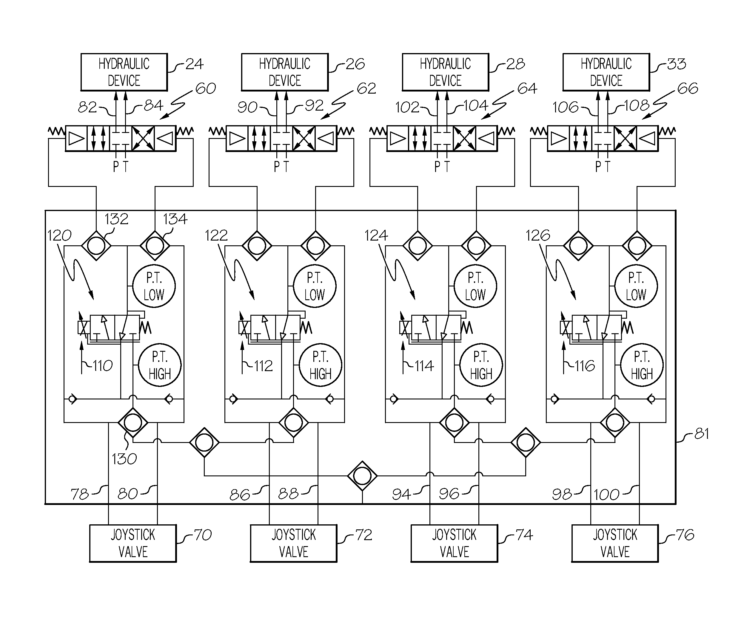
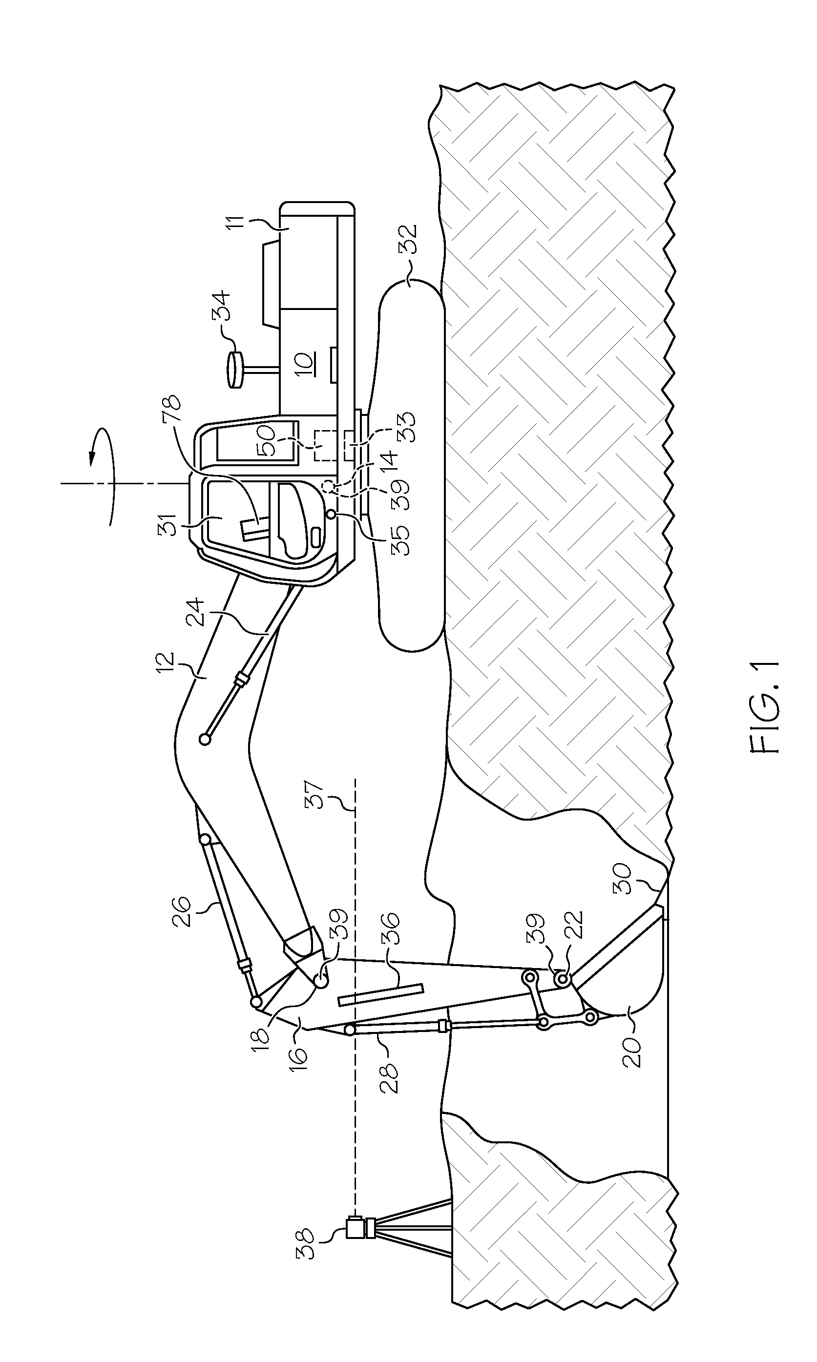
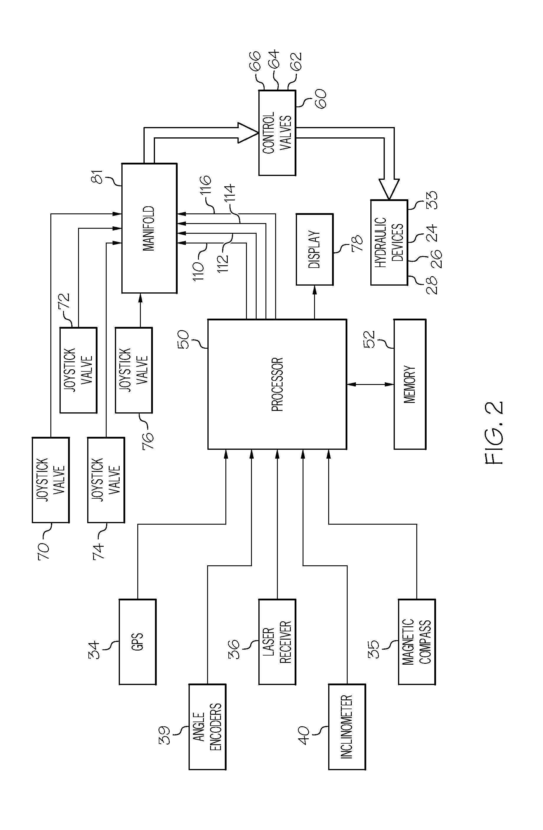
[0016]Excavators commonly utilize a variety of sensors to monitor the positions of various machine elements, and to provide displays of those positions for the assistance of the machine operator. In one typical arrangement, a laser transmitter at the worksite projects a thin laser beam that is rapidly rotated about a generally vertical axis to define a reference plane of laser light. If the plane of laser light is horizontal, and if the excavator carries a laser receiver that detects the beam of light and its position relative to the excavator, it is possible for the excavator control to determine the elevation of the receiver. By reference to other sensors on the excavator which sense inclinations of excavator components, or the included angles between various excavator components, such as the boom and the dipper stick, it is possible to determine the elevation of the digging teeth of the excavator bucket and the cut being made by the excavator bucket. If the desired elevation is n...


PUM


Abstract

A control for an excavator of the type having a plurality of hydraulic cylinders for moving excavator components such that digging is accomplished at a worksite with an excavator bucket or other excavator implement, includes a plurality of hydraulic control valves, each of which is associated with a respective one of the hydraulic cylinders for controlling the application of hydraulic fluid pressure to the respective one of the hydraulic cylinders, and a plurality of manually actuated joystick valves for supplying hydraulic fluid pressure to the respective hydraulic control valves to control the movement of the hydraulic cylinders. The control includes a sensor arrangement for sensing the position of one or more excavator components.

Description

CROSS-REFERENCE TO RELATED APPLICATIONS[0001]NoneSTATEMENT REGARDING FEDERALLY SPONSORED RESEARCH OR DEVELOPMENT[0002]Not Applicable.BACKGROUND[0003]This relates to a control for an excavator of the type in which an operator manually actuates joystick valves to supply hydraulic fluid to hydraulic control valves. The hydraulic control valves then in turn supply hydraulic fluid to hydraulic cylinders or motors to move the various excavator components. In a typical excavator, a boom extends from the excavator chassis, and is pivotally connected to a dipper stick. The dipper stick is pivotally connected to an excavator bucket or other excavator implement. The excavator chassis can be pivoted on the excavator undercarriage, typically by an hydraulic motor. The hydraulic cylinders pivot the boom with respect to the chassis, pivot the dipper stick with respect to the boom, and pivot the bucket or other excavator implement with respect to the dipper stick. Another common excavator configura...

Claims


Application Information

Patent Timeline
IPC IPC(8): F15B3/00
CPCF15B3/00E02F3/435E02F9/2029E02F9/2203E02F9/265
Inventor CARPENTER, HAMISH JOHNPIEKUTOWSKI, RICHARD PAULNICHOLS, MARK
Owner CATERPILLAR TRIMBLE CONTROL TECH
Why Eureka
Try Eureka