
Method of determining fatigue crack lifetime in high-pressure hydrogen environment

a technology of high-pressure hydrogen and lifetime, applied in the direction of instruments, using mechanical means, and analysing solids using sonic/ultrasonic/infrasonic waves, etc., to achieve enhanced accuracy, shorten the total time, and improve the effect of fatigue crack lifetime evaluation

Active Publication Date: 2013-12-19
JAPAN STEEL WORKS LTD
View PDF7 Cites 7 Cited by
  • Summary
  • Abstract
  • Description
  • Claims
  • Application Information

AI Technical Summary

Benefits of technology

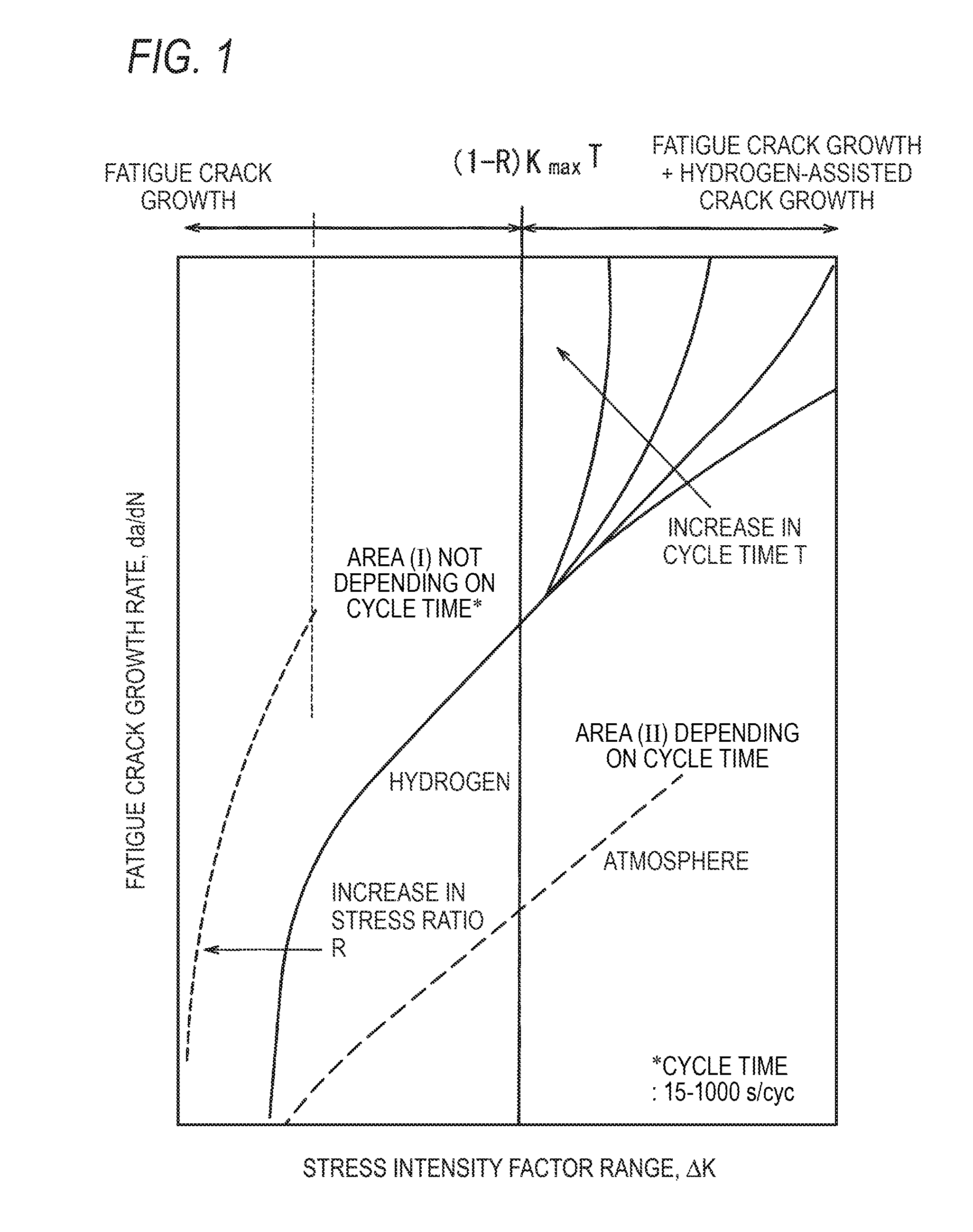
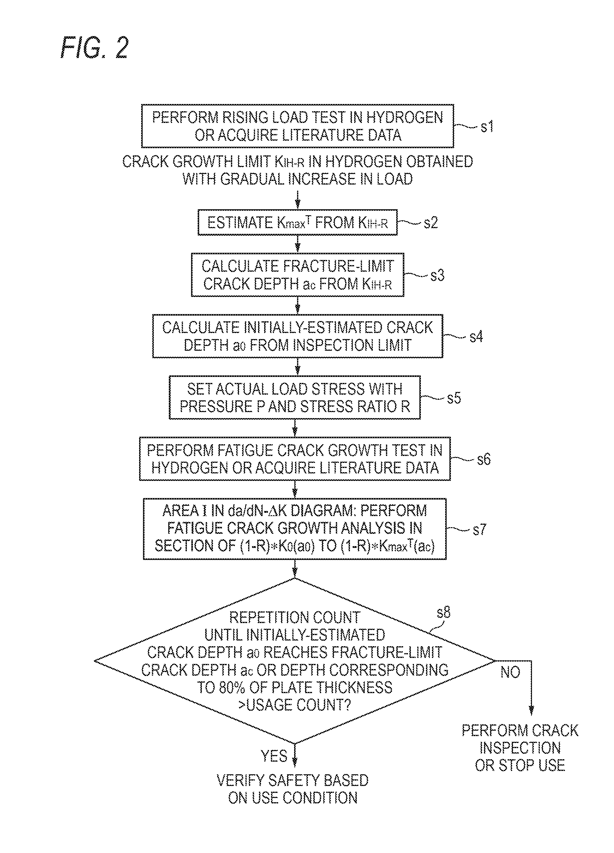
The invention aims to provide an acceleration test method and evaluation procedure that can accurately determine the fatigue crack lifetime of a low-alloy steel pressure component used in high-pressure hydrogen without depending on the steel type, strength, and test conditions. The method utilizes a rising load test at a strain rate of dK / dt=0.08 MPa-m1 / 2 / s or less for a short time, allowing for a faster and more cost-effective evaluation of fatigue crack lifetime compared to the delayed crack test which is the current standard method. By estimating the fatigue crack acceleration starting point KmaxT from the crack-growth threshold stress intensity factor KIH-R which is obtained through the rising load test, the accuracy of fatigue crack lifetime prediction is improved. Overall, this invention provides a more efficient and accurate method for evaluating fatigue crack lifetime for materials used in high-pressure hydrogen environments.

Problems solved by technology

However, most metal materials exhibiting brittleness (=hydrogen environment brittleness) to high-pressure hydrogen gas and even materials exhibiting slight hydrogen environment brittleness to hydrogen have to be actually used for economical reasons.

Method used


Image

  • Method of determining fatigue crack lifetime in high-pressure hydrogen environment
  • Method of determining fatigue crack lifetime in high-pressure hydrogen environment
  • Method of determining fatigue crack lifetime in high-pressure hydrogen environment

Examples


example 1

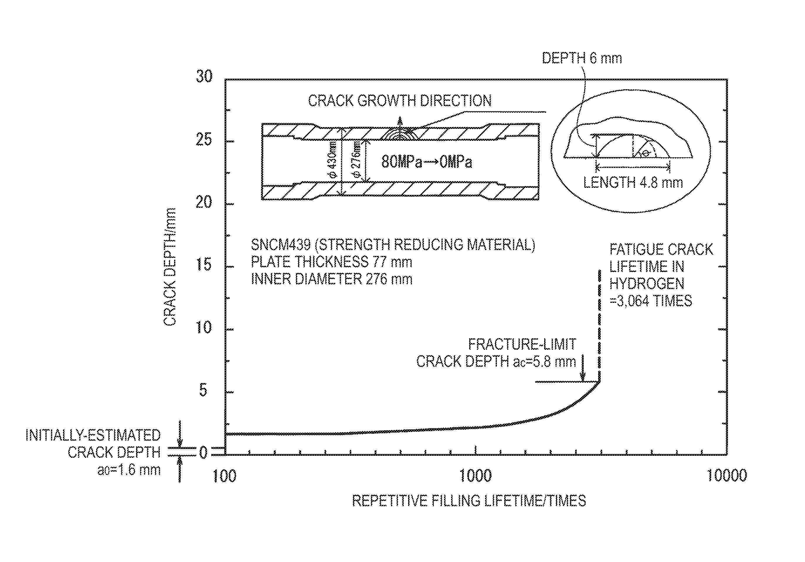
[0085](Correlation between Fatigue Crack Acceleration Starting Point KmaxT and Crack-growth Threshold Stress Intensity Factor KIH-R)

[0086]As examples of low-alloy steel used for a steel pressure accumulator, SCM435 steel and SNCM 439 steel shown in Table 1 were subjected to heat treatment shown in Table 2 and were used as materials under test. Mechanical characteristics of the materials under test are shown in Table 2.

[0087]By performing a fatigue crack growth test in a high-pressure hydrogen environment of 90 MPa or less and evaluating the influence of the repetition cycle time, the fatigue crack acceleration starting point KmaxT for each material under test was obtained.

[0088]A rising load test was performed on the same low-alloy steel and the crack-growth threshold stress intensity factor KIH-R was obtained. A delayed crack test was performed on the same low-alloy steel and the crack-growth threshold stress intensity factor KIH-H was obtained.

[0089]Details of the fatigue testing ...


PUM


Abstract

In a method of determining a fatigue crack lifetime of a low-alloy steel material coming in contact with high-pressure hydrogen in a high-pressure hydrogen environment, estimate a fatigue crack acceleration starting point KmaxT of the low-alloy steel material using a crack-growth threshold stress intensity factor KIH-R obtained through a rising load test on the low-alloy steel material in a high-pressure hydrogen environment. The high-pressure hydrogen environment of the rising load test is a high-pressure hydrogen environment which has the same pressure and atmosphere as in the high-pressure hydrogen environment in which KmaxT is estimated and in which the test temperature tolerance between both environments is ±5° C.

Description

TECHNICAL FIELD[0001]The present invention relates to a method of determining a fatigue crack lifetime which can be applied to a fatigue crack lifetime design or a fatigue crack lifetime diagnosis of a material used in a high-pressure hydrogen environment, and more particularly, to a method of determining a fatigue crack lifetime of a pressure vessel or a pressure component formed of low-alloy steel.BACKGROUND ART[0002]Recently, hydrogen has attracted attention as alternative energy to oil. For high-pressure hydrogen equipment such as pressure accumulators or pipes for storing and supplying hydrogen at a high pressure, there is a demand for materials exhibiting high resistance to high-pressure hydrogen at low cost. However, most metal materials exhibiting brittleness (=hydrogen environment brittleness) to high-pressure hydrogen gas and even materials exhibiting slight hydrogen environment brittleness to hydrogen have to be actually used for economical reasons. Such materials should ...

Claims


Application Information

Patent Timeline
IPC IPC(8): G01N17/00
CPCG01N17/00G01N3/32G01N33/2045G01N2203/0066G01N2203/0073G01N2203/0232
Inventor WADA, YORU
Owner JAPAN STEEL WORKS LTD
Learn More