Rolling bearing assembly device for steering column

a technology of rolling bearings and assembly devices, which is applied in the direction of mechanical equipment, rigid support of bearing units, transportation and packaging, etc., can solve the problems of complex use of rolling bearing assembly devices, inability to allow good distribution of axial preload, devices containing a plurality of components, etc., to encourage good distribution of preload

Active Publication Date: 2013-12-19
AB SKF
View PDF7 Cites 7 Cited by
  • Summary
  • Abstract
  • Description
  • Claims
  • Application Information

AI Technical Summary

Benefits of technology

[0012]More specifically, the present invention seeks to provide a rolling bearing assembly device that is easy to manufacture, to assembly, is of small bulk, economical, and affords good distribution of axial preload over the inner race.
[0015]The annular shape of the radial bearing flange makes it possible to obtain continuous pressure in the circumferential direction between the sleeve and the preload element, i.e. the entire periphery of the radial bearing flange bearing continuously against the preload element, encouraging good distribution of the preload. In addition, the annular shape of the centring portion makes it possible to achieve uniform radial creep of the preload element, likewise encouraging good distribution of the preload.

Problems solved by technology

However, such a rolling bearing assembly device is complex to use and does not allow good distribution of axial preload over the inner race.
However, such rolling bearing assembly devices comprise a plurality of components and a damping element which is complicated to produce.
Furthermore, because the axial dimension of the damping element exceeds the axial dimension of the tolerance ring, such a rolling bearing assembly device is not sufficiently compact in the axial direction.

Method used


Image

  • Rolling bearing assembly device for steering column
  • Rolling bearing assembly device for steering column
  • Rolling bearing assembly device for steering column

Examples


Embodiment Construction

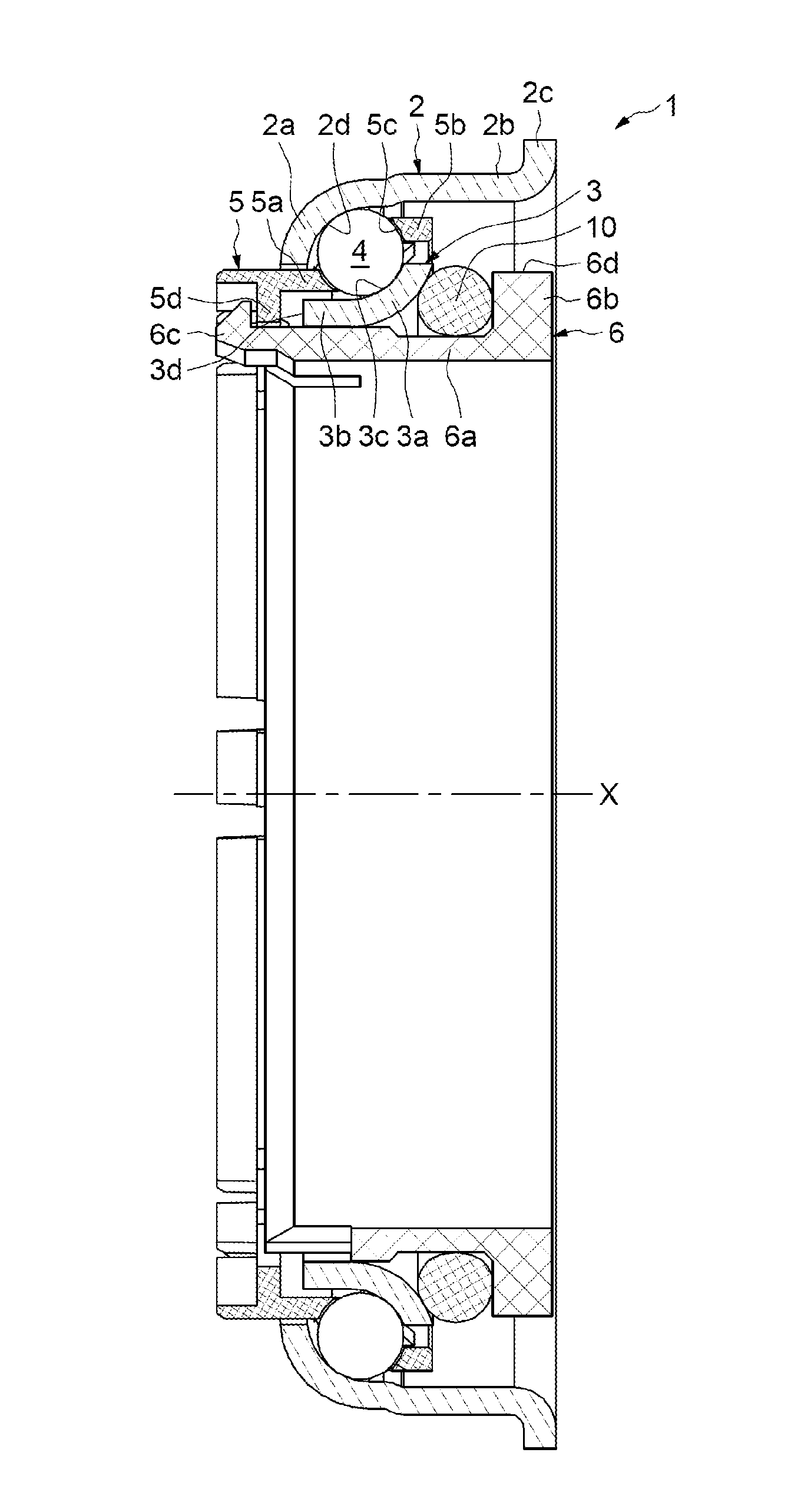
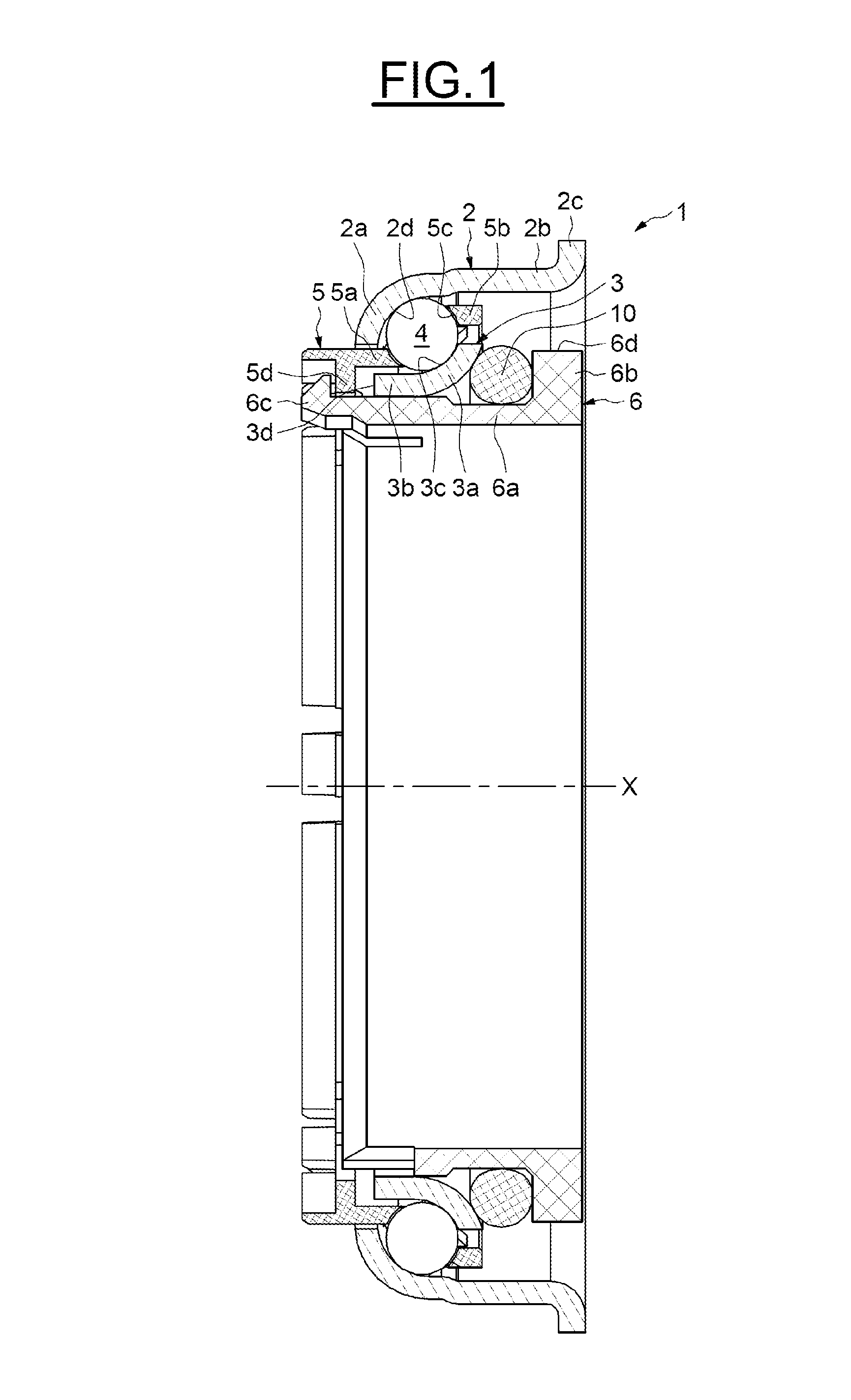
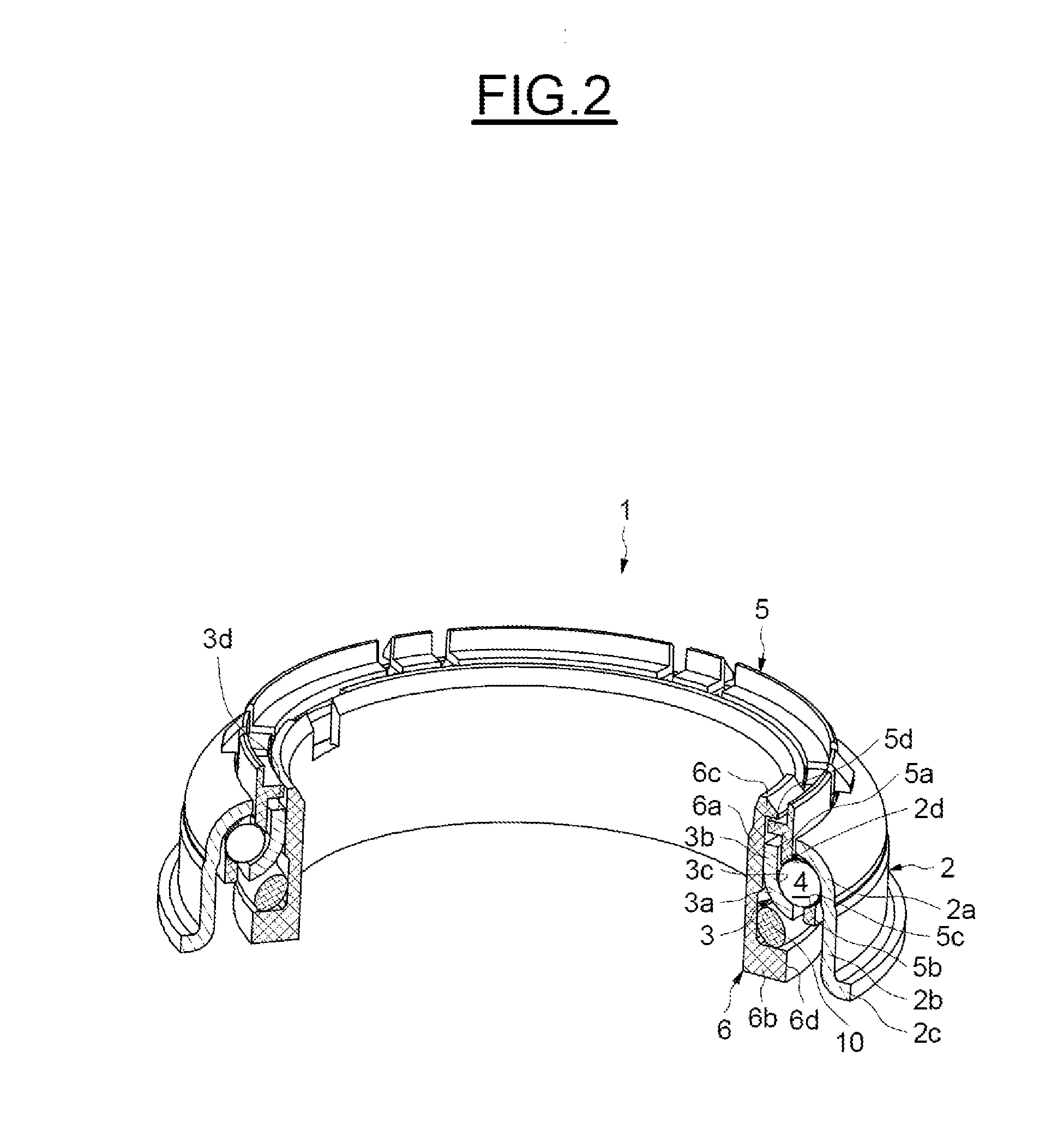
[0037]The rolling bearing assembly device, of axial axis X, referenced 1 in its entirety in FIGS. 1 to 6, is intended to be mounted in a motor vehicle steering column, notably between a tubular housing 14 comprising a bore and a rotary shaft 15 coaxial with the tubular housing 14.

[0038]As illustrated in FIGS. 1 and 2, the rolling bearing assembly device 1 comprises an outer race 2, an inner race 3, a row of rolling elements 4, such as balls for example, a cage 5 for maintaining an even circumferential spacing of the rolling elements 4, and a sleeve 6 or tolerance ring mounted in the inner race 3.

[0039]The outer race, made as a single part, comprises a toroidal portion 2a, an axial portion 2b and a radial rim 2c. The axial cylindrical portion 2b is arranged between the toroidal portion 2a and the radial rim 2c. The toroidal portion 2a has an interior surface that is concave in axial section to form a raceway 2d for the rolling elements 4. The radial rim 2c is directed radially toward...


PUM


Abstract

Rolling bearing assembly device comprising an outer race, an inner race, a row of rolling elements which is arranged between the outer and inner races, a sleeve mounted in the bore of the inner race, and an elastic preload element capable of transmitting an axial preload to the inner race, the elastic preload element being mounted in direct contact with the inner race and being able to be in contact with an annular axial centring portion of the sleeve. A radial bearing flange of the sleeve extends radially from the axial centring portion towards the outside of the device and bears axially over its entire periphery against the elastic preload element.The rolling bearing assembly device comprises an axial retention means bearing axially over its entire periphery against the radial bearing flange of the sleeve.

Description

CROSS-REFERENCE TO RELATED APPLICATIONS[0001]This application claims priority to French Patent Application No. 1255036 filed May 31, 2012 and French Patent Application No. 1353969 filed on Apr. 30, 2013, the contents of which are both herein fully incorporated by reference.FIELD OF THE INVENTION[0002]The present invention relates to the field of rolling bearing assembly devices, notably rolling bearing assemblies used in motor vehicle steering columns.BACKGROUND OF THE INVENTION[0003]Steering columns generally comprise a shaft, one end of which is secured to a steering wheel that drives it and is turned by the driver of the vehicle and the other end of which is secured to mechanical components the role of which is to perform the angular positioning of the wheels of the vehicle. The steering column shaft is mounted such that it can rotate in a tubular housing via two rolling bearing assembly devices each comprising a rolling bearing, generally an angular-contact ball bearing, which a...

Claims


Application Information

Patent Timeline
Patent Type & Authority Applications(United States)
IPC IPC(8): B62D1/16F16C19/06
CPCB62D1/16F16C35/073F16C19/163F16C19/06F16C27/066F16C19/10F16C2326/24F16C25/083F16C33/588F16C27/04F16C25/08
Inventor BUSSIT, SYLVAINJANSEN, DANIELLEPINE, THOMASMONTBOEUF, BRUNO
Owner AB SKF
Why Eureka
Try Eureka