Solar photovoltaic three-phase micro-inverter and solar photovoltaic power generation system

a solar photovoltaic and micro-inverter technology, applied in the direction of d electrical apparatus, ac network circuit arrangement, etc., can solve the problems of high cost of solar difficult design and installation, and complicated implementation, so as to simplify the design and installation of photovoltaic power generation system

Active Publication Date: 2013-12-19
ALTENERGY POWER SYST
View PDF3 Cites 6 Cited by
  • Summary
  • Abstract
  • Description
  • Claims
  • Application Information

AI Technical Summary

Benefits of technology

[0007]Embodiments of the invention intend to solve the technical problems of providing a solar photovoltaic three-phase micro-inverter, to ensure the balance of the three-phase AC current output to the three-phase AC power grid, thereby simplifying the design and installation of the photovoltaic power generation system.

Problems solved by technology

However, a real three-phase micro-inverter will have much more electronic elements than a single-phase micro-inverter, and thus is rather complicated to implement.
This requirement causes difficulty in the design and installation as well as high cost of the solar photovoltaic power generation system.
If the system 100 is rather large in scale, it will be quite difficult to ensure that the environment conditions where the various DC photovoltaic assemblies 102 are located, such as illumination, temperature, etc., are the same, thus it will be very difficult to maintain the balance of the AC currents between the three phases of the input power grid 106, which causes difficulty in the design and installation as well as high cost of the photovoltaic power generation system 100.

Method used


Image

  • Solar photovoltaic three-phase micro-inverter and solar photovoltaic power generation system
  • Solar photovoltaic three-phase micro-inverter and solar photovoltaic power generation system
  • Solar photovoltaic three-phase micro-inverter and solar photovoltaic power generation system

Examples


Embodiment Construction

[0038]The invention will be further described in conjunction with the following specific embodiments and the drawings, although the invention is not so limited.

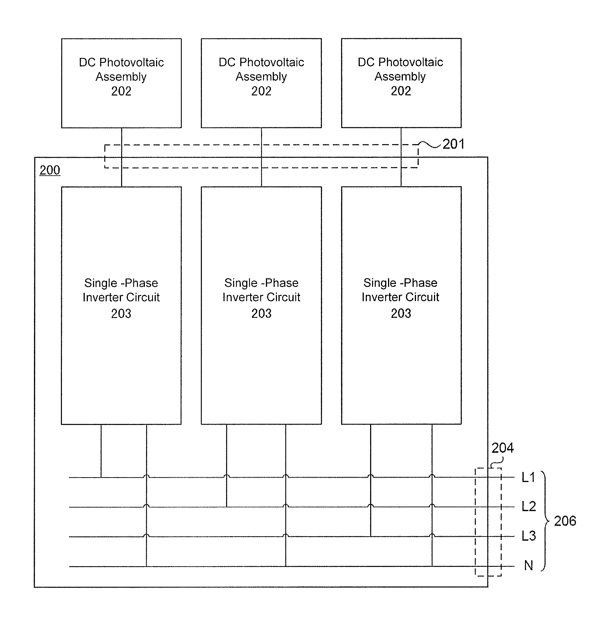
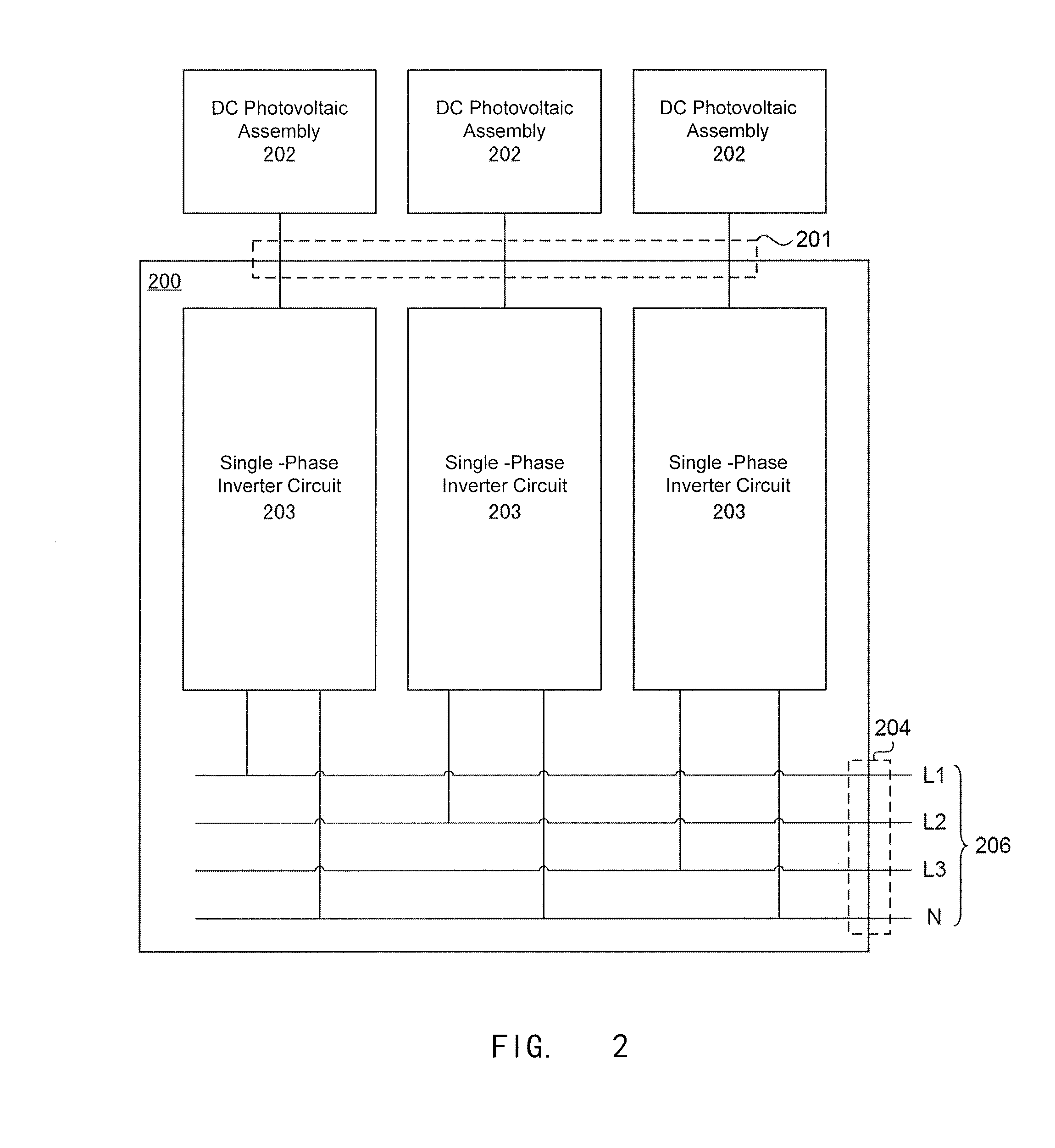
[0039]FIG. 2 is a schematic block diagram of a solar photovoltaic three-phase micro-inverter in an embodiment of the invention. As shown, the three-phase micro-inverter 200 may comprise:

[0040]DC terminals 201, coupled with three DC photovoltaic assemblies 202 which are adjacent to each other, for receiving DC currents generated by the DC photovoltaic assemblies 202;

[0041]three single-phase inverter circuits 203 having input terminals coupled respectively with the three DC photovoltaic assemblies 202 via the DC terminals 201, for converting the DC currents generated by the three DC photovoltaic assemblies 202 to single-phase AC currents, respectively, wherein the above three single-phase inverter circuits 203 may employ completely the same structure;

[0042]AC terminals 204 which include four wires and couple with a three-phase ...


PUM


Abstract

A solar photovoltaic three-phase micro-inverter comprises: DC terminals, coupled with three DC photovoltaic assemblies adjacent to each other; three single-phase inverter circuits having input terminals coupled respectively with the three DC photovoltaic assemblies via the DC terminals, for converting the DC currents generated by the three DC photovoltaic assemblies to AC currents, respectively; AC terminals coupled with a three-phase AC power grid; wherein output terminals of each single-phase inverter circuit are coupled respectively with a neutral wire and one of the three phases of the three-phase AC power grid. A solar photovoltaic power generation system is also provided. The three single-phase inverter circuits can be integrated as above Because the three DC photovoltaic assemblies on one three-phase micro-inverter are disposed adjacently and have similar environment conditions, such as illumination, temperature, etc., the three-phase AC current can be well balanced.

Description

CROSS-REFERENCES TO RELATED APPLICATIONS[0001]This application is a Continuation of International Application No. PCT / CN2012 / 070048, International Filing Date Jan. 5, 2012, and which claims the benefit of CN patent application No. 201110044171.0, filed Feb. 23, 2011, the disclosures of both applications being incorporated herein by reference.TECHNICAL FIELD[0002]The invention relates to the field of solar photovoltaic technology, and more particularly, to a solar photovoltaic three-phase micro-inverter and a solar photovoltaic power generation system.BACKGROUND ART[0003]The inverter in a solar photovoltaic power generation system recently trends to employ distributed micro inverters (micro-inverters). The micro-inverter may provide maximum power point control for each direct current (DC) photovoltaic assembly, such that each DC photovoltaic assembly can produce a maximum energy, thereby improving the performance of the whole solar photovoltaic power generation system. Furthermore, t...

Claims


Application Information

Patent Timeline
Patent Type & Authority Applications(United States)
IPC IPC(8): H02J3/38
CPCH02J3/38H02J2300/24H02J3/381Y02E10/56
Inventor LUO, YUHAO
Owner ALTENERGY POWER SYST
Why Eureka
Try Eureka