Method and device for operating a drive device

a drive device and drive shaft technology, applied in the direction of propulsion parts, transportation and packaging, gas pressure propulsion mounting, etc., can solve the problem of low driving speed and achieve the effect of high frictional loss and driving speed

Active Publication Date: 2013-12-19
ROBERT BOSCH GMBH
View PDF2 Cites 6 Cited by
  • Summary
  • Abstract
  • Description
  • Claims
  • Application Information

AI Technical Summary

Benefits of technology

[0008]In order to start the combustion engine, particularly at low driving speeds, provision is therefore made in the inventive method for operating the drive device of the motor vehicle for the second clutch to be engaged during the electric driving operation so as to drive the combustion engine by means of the electric machine, for a gear to be simultaneously or subsequently engaged in the first sub-transmission, said gear having a lower gear ratio (i.e. a higher gear) than the engaged driving gear of the second sub-transmission, for the first clutch to then be brought into a slip position and the second sub-transmission to subsequently be brought into a neutral position, for the rotational speed of the electric machine to subsequently be increased at least to a starting rotational speed for the combustion engine with the slip of the first clutch being adjusted to maintain a forward torque of the motor vehicle and for the combustion engine to be started once its starting rotational speed has been reached. The inventive method ensures that the combustion engine can also be started at very low speeds and at the ensuing low rotational speeds without the loss of forward torque. This is substantially achieved by virtue of the fact that a gear is engaged in the first sub-transmission, which gear has a lower gear ratio than the engaged driving gear of the second sub-transmission. In so doing, the combustion engine is coupled to a higher gear than the electric machine—as viewed in the direction of the power flow from the respective drive unit to the driving wheels of the motor vehicle—, whereby a torque flows from the very slowly rotating (driven) combustion engine via the slipping first clutch in the direction of the driving wheels. A power flow to the driving wheels is thereby always ensured, wherein the combustion engine can simultaneously be brought to a rotational speed which is sufficient for starting said combustion engine, the so-called starting rotational speed, at low driving speeds by means of the adjusted slip of the first clutch. Particularly a separate starter motor for the combustion engine can be eliminated by the advantageous method, and therefore the drive device is preferably provided without a separate starter motor. In this situation, a higher frictional loss at the slip clutch however results if the driving speed continues to be low.

Problems solved by technology

In this situation, a higher frictional loss at the slip clutch however results if the driving speed continues to be low.

Method used


Image

  • Method and device for operating a drive device
  • Method and device for operating a drive device
  • Method and device for operating a drive device

Examples


Embodiment Construction

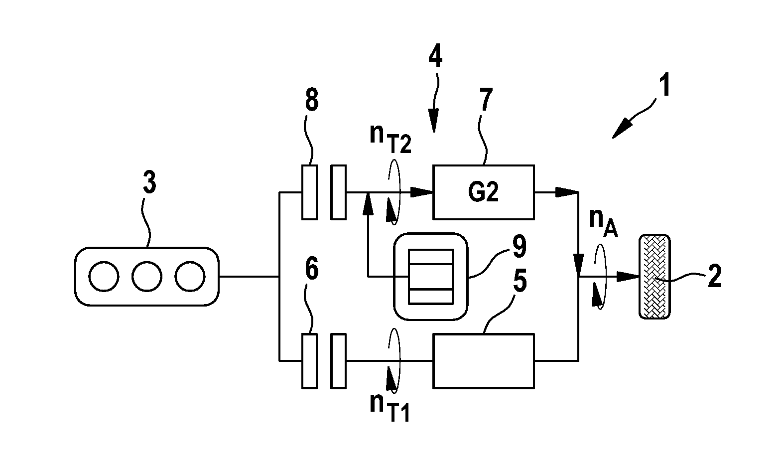
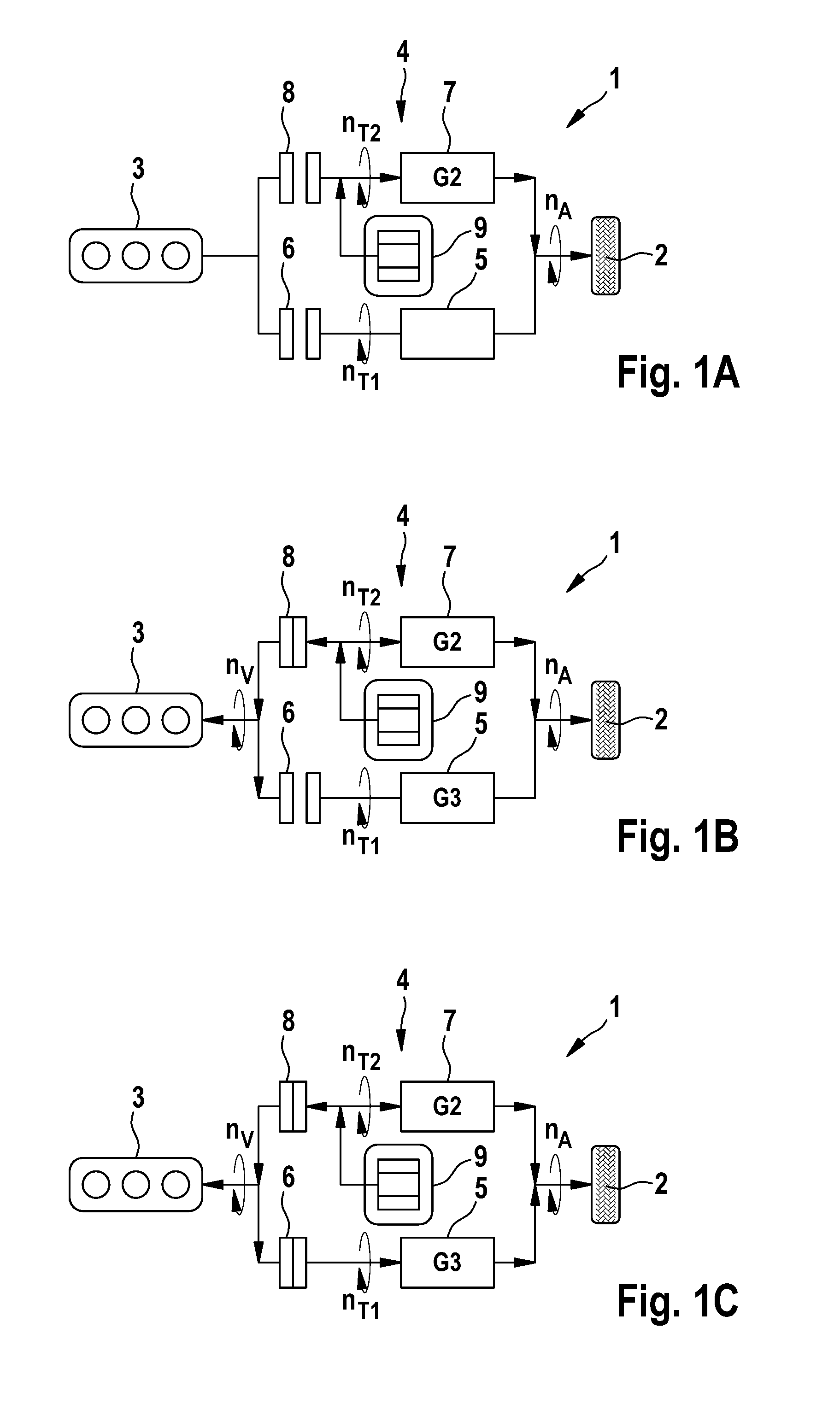
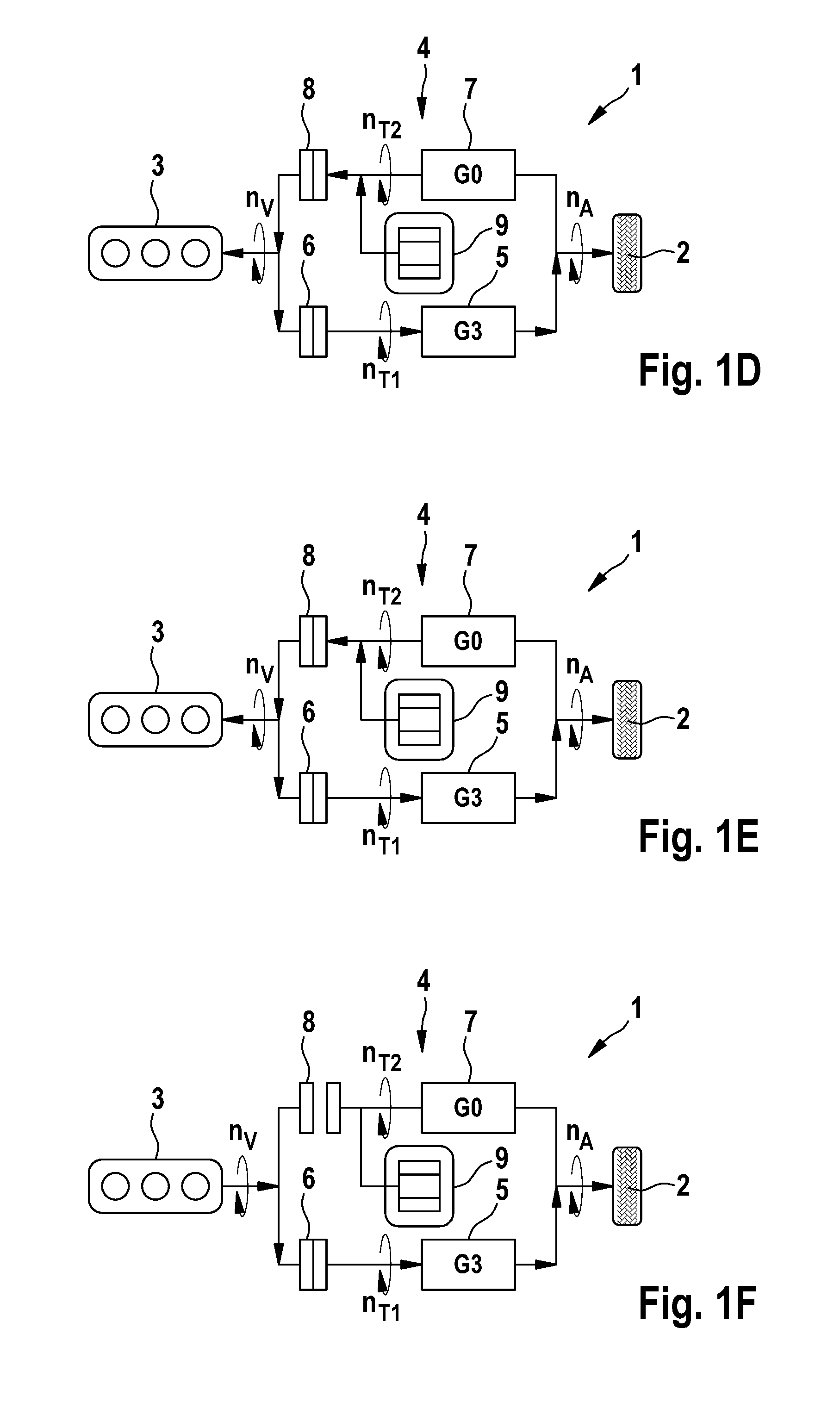
[0022]FIGS. 1A to 1K show a simplified depiction of a drive device 1, which is used to drive driving wheels 2, of which only one is indicated, of a motor vehicle not shown in detail here. The drive device 1 is designed as a hybrid drive and in so doing comprises a combustion engine 3, which is operatively connected to the driving wheels 2 via a dual clutch transmission. The dual clutch transmission 4 comprises a first sub-transmission 5, with which a first clutch 6 is associated, as well as a second sub-transmission 7, with which a second clutch is associated. At least the odd gears 1, 3 and if applicable 5 can be adjusted in the first sub-transmission 5; and at least the even gears 2, 4 and if applicable 6 can be adjusted in the second sub-transmission 7. The higher the gear is, the lower the adjusted gear ratio i thereof is. Hence, the first gear G1 in the present embodiment has a gear ratio of i=16, the second gear G2 a gear ratio of i=10 and the third gear G3 a gear ratio of i=6...


PUM


Abstract

The invention relates to a method for operating a drive device (1) of a motor vehicle, said drive device (1) comprising at least one combustion engine (3) and at least one electric machine (9), as well as a dual clutch transmission (4) which can be functionally connected to the combustion engine (3) and which comprises a first sub-transmission (5), a first clutch (6) being associated therewith, and a second sub-transmission (7), a second clutch (8) and the electric machine (9) being associated therewith. In a purely electrical driving operation, the electric machine (9) is operated in a motorised manner, a driving gear is engaged in the second sub-transmission (7), and both clutches (6, 8) are disengaged. According to the invention, in order to start the combustion engine (3) during the electric driving operation, the second clutch (8) is engaged so as to drive the combustion engine (3) by means of the electric machine (9), a gear is engaged in the first sub-transmission (5), said gear having a lower gear ratio than the engaged driving gear of the second sub-transmission (7), the first clutch (6) is brought into a slip position and the second sub-transmission (7) is subsequently brought into a neutral position, the rotational speed of the electric machine (9) is increased at least to a starting rotational speed for the combustion engine (3) with the slip of the first clutch (6) being adjusted to maintain a forward torque of the motor vehicle, and the combustion engine (3) is started once its starting rotational speed has been reached. In addition, the invention relates to a device for operating a drive device of a motor vehicle.

Description

BACKGROUND OF THE INVENTION[0001]The invention relates to a method for operating a drive device of a motor vehicle, said drive device comprising at least one combustion engine and at least one electric machine, as well as a dual clutch transmission which can be functionally connected to the combustion engine and which comprises a first sub-transmission, a first clutch being associated therewith, and a second sub-transmission, a second clutch and the electric machine being associated therewith. In a purely electrical driving operation, in particular for generating a forward torque for the motor vehicle or, respectively, to the driving wheels of said motor vehicle, the electric machine is operated in a motorized manner, a driving gear is engaged in the second sub-transmission and both clutches are disengaged.[0002]The invention further relates to a device for operating a drive device of a motor vehicle, in particular for carrying out the method described above, said drive device compr...

Claims


Application Information

Patent Timeline
Patent Type & Authority Applications(United States)
IPC IPC(8): B60W20/00
CPCB60W20/10Y10S903/902B60W10/02B60W10/06B60W10/08B60W10/113B60W20/00B60W30/192Y02T10/62B60W20/40B60W20/30
Inventor MAASS, ALEXANDERRICHTER, BOYKE
Owner ROBERT BOSCH GMBH
Why Eureka
Try Eureka