Apparatus for testing a filter

a filter and apparatus technology, applied in the field of apparatus and filter filter apparatus testing, can solve the problems of not allowing an operator to enter information, prior known devices cannot change the mode of operation of the testing system without directly interacting with the base unit, and the prior known devices have several significant limitations, so as to prevent noise suppression and facilitate signal noise suppression

Active Publication Date: 2013-12-26
HAMILTON ASSOCS
View PDF55 Cites 4 Cited by
  • Summary
  • Abstract
  • Description
  • Claims
  • Application Information

AI Technical Summary

Benefits of technology

[0010]Yet still a further object of a preferred embodiment of the present invention is to provide a system for testing a filter having a base unit and a probe operably associated with the base unit where the system can readily detect when the probe is connected to the base unit and alter at least one operational characteristic of the base unit when the probe is connected to the base unit.
[0011]Yet another object of a preferred embodiment of the present invention is to provide a system for testing a filter that can readily perform signal noise suppression on an upstream test sample and a downstream test sample.
[0012]Still a further object of a preferred embodiment of the present invention is to provide a system for testing a filter having a base unit and probe operably connected to the base unit where the system is configured to prevent noise suppression of a downstream test sample when the probe is connected to the base unit.

Problems solved by technology

Prior known systems have several significant limitations.
One such drawback is the inability of the prior known devices to change the mode of operation of the testing system without directly interacting with the base unit.
Also, prior known systems do not allow an operator to enter information regarding a filter being tested from a location remote from the base unit.
Further, prior known devices do not allow the testing unit to readily test a filter where the test sample (typically aerosol) was unstable.
Further, prior known systems do not permit a residual test sample located in the probe and / or base unit to be automatically exhausted when the testing system changes between testing an upstream sample and downstream sample.
Moreover, prior known systems have not been configured to detect when the probe is connected to the base unit and alter the operating capabilities of the testing system when the probe is connected to the base unit.

Method used


Image

  • Apparatus for testing a filter
  • Apparatus for testing a filter
  • Apparatus for testing a filter

Examples


Embodiment Construction

[0035]The most preferred form of the invention will now be described with reference to FIGS. 1-15. The appended claims are not limited to the most preferred embodiment and no term used herein is to be given a meaning other than its ordinary meaning unless expressly stated otherwise.

FIGS. 1 Through 15

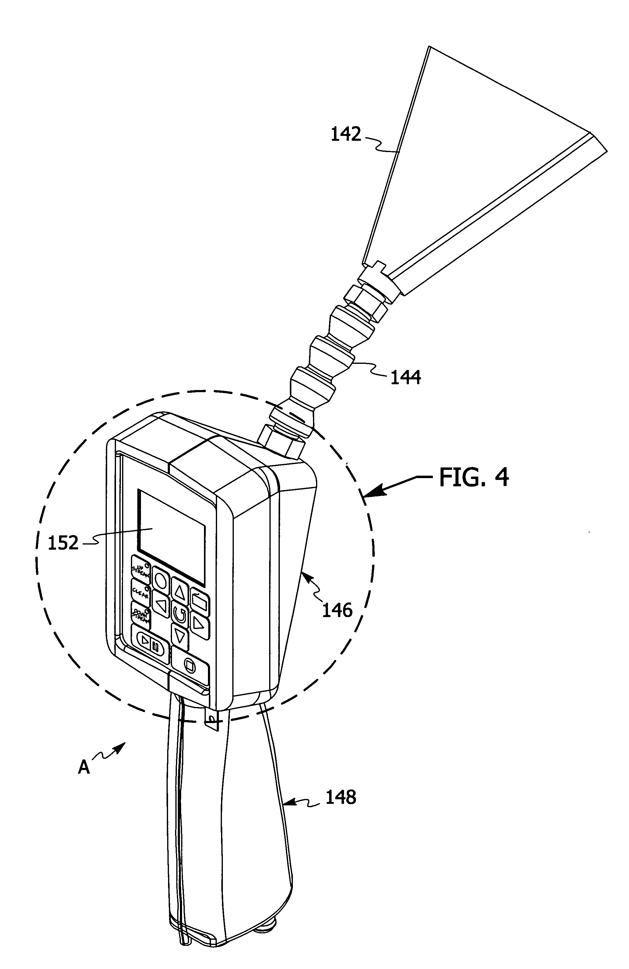
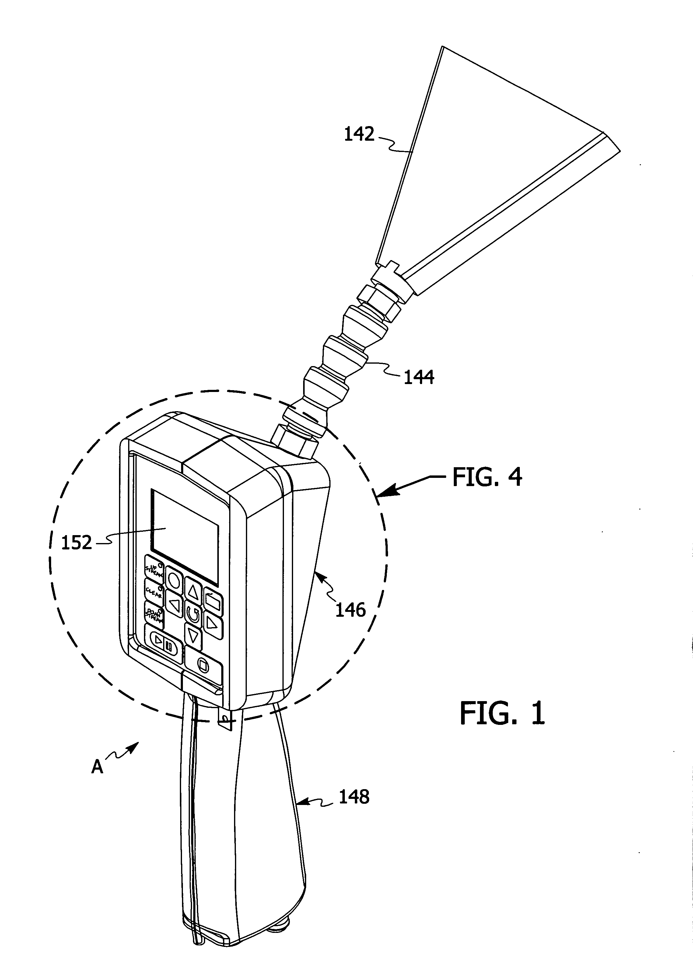
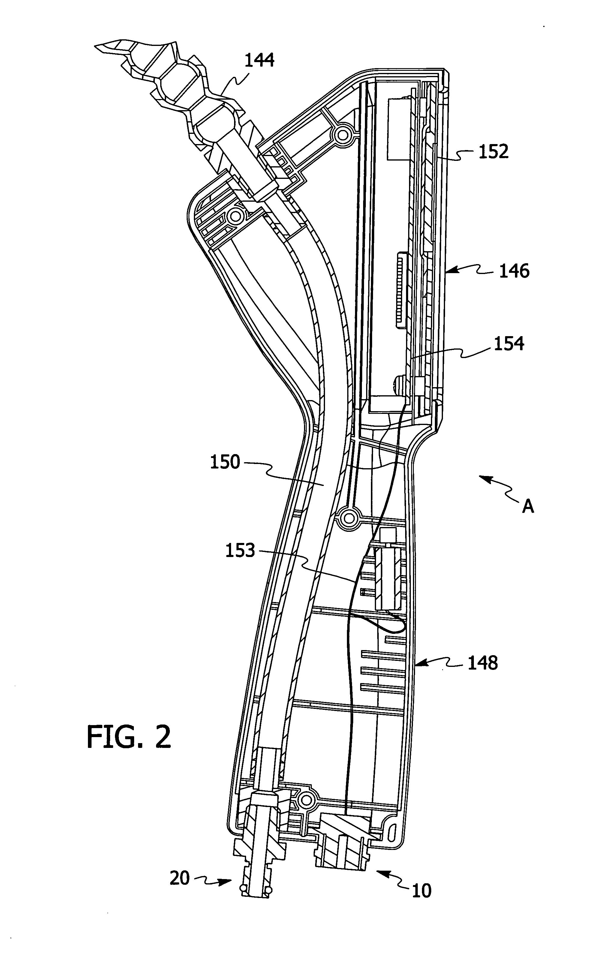
[0036]Referring to FIGS. 1 to 15, the components of the most preferred form of filter testing system for testing filters are illustrated in one of many possible configurations. Preferably, the filter testing system is an in situ filter testing system, i.e., the filter can be tested when located in its normal operating position.

[0037]The filter testing system preferably includes a probe A (see FIGS. 1 to 4), a coupling assembly B (see FIG. 5) and a base unit C (see FIGS. 6 to 15). The coupling assembly B operably connects the probe A to the base unit C. Referring to FIG. 5, coupling assembly B includes an electrical coupler 2 having electrical connectors 4 and 6 disposed at opposite ends....


PUM

PropertyMeasurementUnit
residual testaaaaaaaaaa
noiseaaaaaaaaaa
concentrationaaaaaaaaaa

Abstract

A preferred form of the invention is directed to a system and method used to test filters. The system preferably includes a base unit and a probe operably associated with the base unit. The probe is configured to be deployed adjacent the filter being tested while the filter is located in an operating position. The probe is further configured to allow an operator to vary the mode of operation of the base unit from the probe. The system is configured to automatically exhaust any residual test sample from the base unit and the probe when the system changes between testing a sample upstream and downstream of the filter. The system further includes noise suppression on at least one of the upstream test sample and downstream test sample. The system further is configured to detect when the probe is connected to the base unit.

Description

FIELD OF THE INVENTION[0001]The preferred form of the present invention is directed to an apparatus and method for testing a filter. In the most preferred form, the present invention is directed to an apparatus and method for testing a filter in situ, i.e., the normal operating position of the filter.BACKGROUND OF THE INVENTION[0002]Various devices have been used to test leakage of various filters employed in bio safety cabinets, pharmaceutical clean rooms, animal testing laboratories and nuclear environments. These devices have included photometers used in conjunction with aerosol generators to measure how well a filter is performing. Typically, an aerosol with a known concentration is introduced before or upstream of the filter and the photometer is operably connected to the downstream side of the filter to measure any leakage of the aerosol through the filter. Photometers typically utilize forward light scattering to measure any leakage of aerosol through the filter being tested....

Claims


Application Information

Patent Timeline
Patent Type & Authority Applications(United States)
IPC IPC(8): G01N7/00
CPCG01N15/06G01N2015/0662
Inventor PEACOCK, RYAN VALLARGENT, DONALD JONATHANMASSET, SYLVAIN DOMINIQUE
Owner HAMILTON ASSOCS
Why Eureka
Try Eureka