Clothes treatment appliance with transfer pipe

a technology of transfer pipe and cloth, which is applied in the direction of cleaning with liquids, other washing machines, textiles and paper, etc., can solve the problems of ineffective filtering, condensation effectiveness, and breakdown of the condenser function, and achieve the effect of improving the effectiveness of cleaning a water-cleanable unit and simple clothes treatmen

Inactive Publication Date: 2013-12-26
BSH BOSCH & SIEMENS HAUSGERAETE GMBH
View PDF2 Cites 32 Cited by
  • Summary
  • Abstract
  • Description
  • Claims
  • Application Information

AI Technical Summary

Benefits of technology

[0009]It is an object of the present invention to overcome or mitigate at least some of the problems associated with the prior art and in particular to provide a relatively simple clothes treatment appliance with an improved effectiveness for cleaning a water-cleanable unit, in particular condenser.
[0010]An object is achieved by a clothes treatment appliance, including a transfer pipe leading to a water-cleanable unit of the clothes treatment appliance, wherein the transfer pipe includes at least one water diversion means that is adapted to divert at least part of the water exiting the transfer pipe in a sideway direction. The diverted water hits the condenser in areas next to the region that would be cleaned by non-diverted water. This enlarges the area or region of the water-cleanable unit that can be effectively cleaned. There is no need for a large distance between the transfer pipe and the water-cleanable unit such that a high momentum of water can be maintained the water. Also, using the water diversion means enables a precisely formed and directed water gush. It is an additional advantage that the sideway direction lets the water gush hit the lint in a direction differently from the vertical direction of condensate running down the condenser which enables a more effective removal of this lint.

Problems solved by technology

However, filters are not effective enough to separate all the particles or residue from the process air flow.
These lint agglomerations reduce the condensation effectiveness and may cause a breakdown of the condenser function over time.
However, the water gush often cannot completely clean the condenser, and typically a certain amount of lint remains.
However, this greatly reduces the momentum of the water hitting the condenser and thus its ability to effectively remove sticky residue.
However, implementation of this cleaning method is rather complex.

Method used


Image

  • Clothes treatment appliance with transfer pipe
  • Clothes treatment appliance with transfer pipe
  • Clothes treatment appliance with transfer pipe

Examples


Embodiment Construction

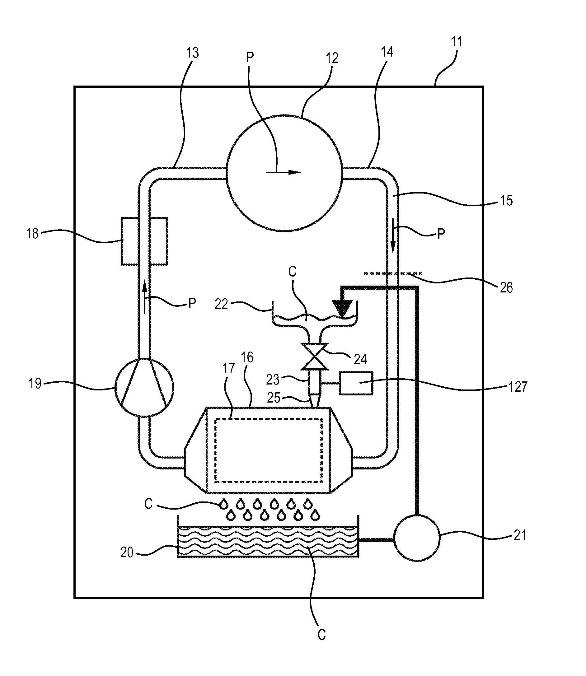
[0065]FIG. 1 shows a clothes treatment appliance realized as a household drying appliance 11, in particular a clothes dryer. The drying appliance 11 comprises a clothes container in form of a rotatable clothes drum 12. The drum 12 is connected to an air inlet section 13 and an air outlet section 14 of a process air channel 15. Warm air entering the drum 12 via the air inlet section 13 can dry the clothes contained in the drum 12. The resulting warm and wet process air P leaves the drum 12 through the air outlet section 14 and flows to a process air condenser 16 that cools the process air P. Thus, at the condenser 16, the process air P precipitates. To cool the process air P, the condenser 16 has several plate-like cooling blades 17 that are arranged in a parallel fashion (which in the shown drawing are oriented in parallel to and are spaced apart perpendicular to the viewing plane).

[0066]The condenser 16 and its cooling blades 17, respectively, may be water-cooled. In this case, the...


PUM


Abstract

A clothes treatment appliance includes a transfer pipe leading to a water-cleanable unit of the clothes treatment appliance. The transfer pipe includes a water diverter that diverts part of the water exiting the transfer pipe in a sideway direction. A method for cleaning a water-cleanable unit of a clothes treatment appliance includes releasing water into a transfer pipe and diverting part of the water exiting the transfer pipe in a sideway direction.

Description

BACKGROUND OF THE INVENTION[0001]The invention relates to a clothes treatment appliance, in particular a clothes dryer, including a transfer pipe leading to a water-cleanable unit of the clothes treatment appliance.[0002]A typical condensation-type clothes dryer (as such or as a washer-dryer in combination with a washing function) includes a laundry or clothes container (e.g. a rotatable clothes drum) that is connected to an air inlet and an air outlet of a process air channel. Warm air entering the clothes container via the air inlet of the process channel dries the clothes or laundry. The resulting warm and wet process air leaves the clothes container through the air outlet of the process air channel and flows to a process air condenser that cools the process air. At the condenser, the humidity contained by the process air precipitates. Thus, behind the condenser (with respect to a flow direction of the process air) the process air is cool and dry and flows to a heater which heats...

Claims


Application Information

Patent Timeline
Patent Type & Authority Applications(United States)
IPC IPC(8): B08B3/04D06F39/00
CPCD06F39/10D06F58/22D06F58/24
Inventor BOMMELS, RALFGEMUNDEN, BERNDHEJURGENPROSEANIC, VLADIMIRVISNEPOLSCHI, SVETLANA
Owner BSH BOSCH & SIEMENS HAUSGERAETE GMBH
Why Eureka
Try Eureka