Resistive structure and resistive voltage divider arrangement

a resistive structure and resistive voltage divider technology, applied in the direction of resistor details, resistors with plural resistive elements, instruments, etc., can solve the problems of increasing complexity and cost, worse resistance drift, and increasing resistance value dri

Active Publication Date: 2013-12-26
ABB (SCHWEIZ) AG
View PDF4 Cites 7 Cited by
  • Summary
  • Abstract
  • Description
  • Claims
  • Application Information

AI Technical Summary

Benefits of technology

[0013]An exemplary embodiment of the present disclosure provides a resistive voltage divider which includes a first resistor and a second resistor electrically connected in series, where each resistor is made of one or more traces of electrically resistive film material applied onto a cylindrical insulating substrate. At least one of the traces has a helix-like shape and is applied onto the substrate by direct printing.

Problems solved by technology

All these process steps add to the complexity and to the cost to produce a certain structure or device, and it is therefore of high interest to reduce the number of printing steps, especially as each printing step requires additional process operations and may cause errors or irregularities in the printed structures.
Trimming is performed using techniques such as laser or mechanical cutting and induces stresses in the resistive structure which impact the long term stability and causes drifts of the resistance value.
It is the case that even after several days of stabilization the stresses are not fully removed and the resistance drift is worse than of an equivalent structure which was entirely produced by direct printing without trimming.
The materials with high resistivity values often have poorer performance parameters such as temperature coefficient, voltage coefficient, noise, and stability.
However, when the value of the resistance needs to be large like in all high voltage applications the parasitic value of the inductance is completely negligible and the parasitic capacitance becomes more critical.
However, they are not suitable for high voltage levels because the serpentine shape engenders very non uniform distribution of the electric field with very high maximum values.
The alternating distribution of the electric field intensity with very low minima and very high maxima is not suitable for withstanding high voltage.
Moreover, a significant gap between the rounded corners of the serpentine pattern needs to be left free both for production and electrical reasons.
A small gap is difficult to fabricate but will also lead to strong electric fields between the corners of the serpentine pattern and poor voltage withstand of the resistor.
The serpentine structure makes therefore ineffective use of both the length and the circumference of the resistor for withstanding the applied voltage.
For operation at a certain maximum voltage, the size of the resistive structure must be sufficiently big in order to keep the high peak values of the electric field intensity under practical limits, resulting in large size and cost of the device.
Additionally, the high peak values of the electric field intensity generate stresses in the resistive structure and may lead to drifts of the resistance value, and therefore poor accuracy.

Method used


Image

  • Resistive structure and resistive voltage divider arrangement
  • Resistive structure and resistive voltage divider arrangement
  • Resistive structure and resistive voltage divider arrangement

Examples


Embodiment Construction

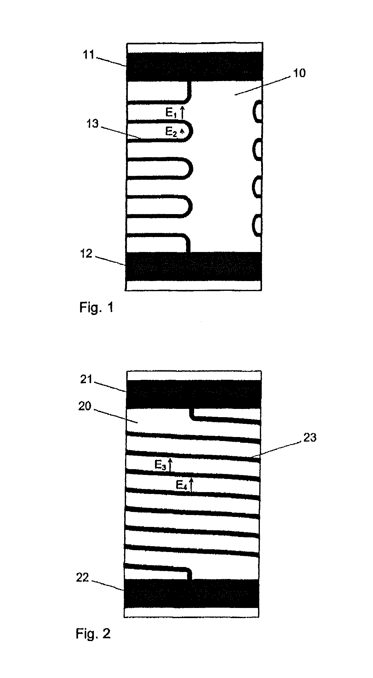
[0021]Exemplary embodiments of the disclosure provide a solution for a resistive structure with an improved profile of the electric field and an almost uniform distribution of the intensity of the electric field. The resistive structure can be directly printed on the surface of a insulating substrate using a screen printing technique, for example. Furthermore, exemplary embodiments of the present disclosure provide a resistive voltage divider or voltage divider arrangement having superior accuracy, higher voltage withstand, smaller size, and lower cost than presently known devices.

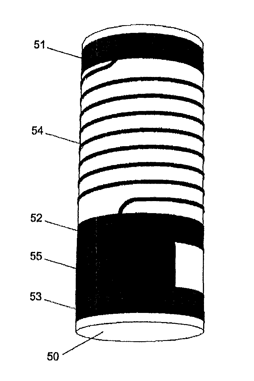
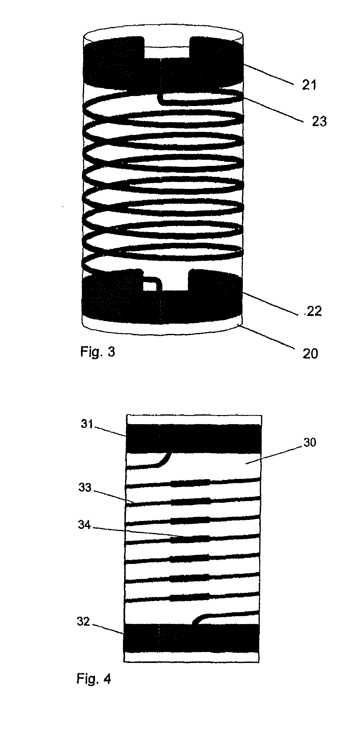
[0022]Exemplary embodiments of the present disclosure provide a resistive structure with an improved electric field profile deposited on the surface of a cylindrical insulating substrate, wherein at least one resistive path or trace has the shape looking approximately like a helix and is directly printed on the surface of the insulating substrate. Additional exemplary embodiments and developments as well a...


PUM


Abstract

A resistive structure has an improved electric field profile deposited on the surface of a cylindrical insulating substrate. At least one resistive path or trace is provided with a helix-looking shape and is directly printed on the surface of the insulating substrate. A resistive voltage divider includes first and second resistors electrically connected in series, where each resistor is made of one or more traces of electrically resistive film material applied onto a cylindrical insulating substrate. At least one of the traces is shaped like a helix and is applied onto the substrate by direct printing.

Description

RELATED APPLICATIONS[0001]This application claims priority as a continuation application under 35 U.S.C. §120 to PCT / EP2012 / 000818, which was filed as an International Application on Feb. 25, 2012 designating the U.S., and which claims priority to European Application 11001582.3 filed in Europe on Feb. 25, 2011. The entire contents of these applications are hereby incorporated by reference in their entireties.FIELD[0002]The present disclosure relates to a resistive structure with an improved electric field profile deposited on the surface of an insulating substrate, and to a resistive voltage divider arrangement including such a resistive structure having first and second resistors connected in series.BACKGROUND INFORMATION[0003]A resistive voltage divider is provided for transforming a primary voltage to a proportional secondary voltage, whereas the secondary voltage is significantly smaller than the primary voltage, for example, between 10 times and 100000 times. For practical app...

Claims


Application Information

Patent Timeline
Patent Type & Authority Applications(United States)
IPC IPC(8): H01C1/00G01R19/00
CPCH01C1/00G01R19/0084H01C7/003H01C7/22H01C17/065G01R15/04
Inventor HOZOI, ADRIANDISSELNKOTTER, ROLFPAVLAS, MAREK
Owner ABB (SCHWEIZ) AG
Why Eureka
Try Eureka