Tire monitoring system and method

a monitoring system and tire technology, applied in the direction of optical radiation measurement, instruments, transportation and packaging, etc., can solve the problems of not being able to accurately reflect, not being able to accurately detect the temperature of the tire tread, etc., to achieve accurate detection of tire tread temperature, fast response time, and reliable and accurate sensor data.

Inactive Publication Date: 2013-12-26
GM GLOBAL TECH OPERATIONS LLC
View PDF5 Cites 12 Cited by
  • Summary
  • Abstract
  • Description
  • Claims
  • Application Information

AI Technical Summary

Benefits of technology

[0005]An advantage of an embodiment is that measuring the tire carcass temperature has a fast response time for detecting changes in tire tread temperature. Also, the mounting location of the sensor measuring the temperature allows the sensor to remain clean (free of dirt or other debris), thus maintaining reliable and accurate sensor data reliable and accurate over a long time period. Further, the temperature is taken without any tire contact yet accurately detects tire tread temperature. By providing the tire temperature data, the vehicle control systems can account for differences in tire traction that may occur at different tire temperatures. In addition, the advantages of the invention are provided while adding little weight.

Problems solved by technology

However, this is a slow changing measurement relative to the tire tread temperature and does not necessarily accurately reflect the tire tread temperature for various vehicle operating conditions.
Others use a thermocouple and slip ring, but these types of arrangements may not be as durable as desired and may be more costly than is desired for a vehicle.
Still others employ exterior mounted infrared sensors directed toward the tire tread, but these sensors can become dirty relatively quickly, which may cause them to stop working.
Some have employed tire temperature modeling to estimate the tire tread temperature, but this may not be as accurate as desirable for all vehicle applications.

Method used


Image

  • Tire monitoring system and method
  • Tire monitoring system and method
  • Tire monitoring system and method

Examples


Embodiment Construction

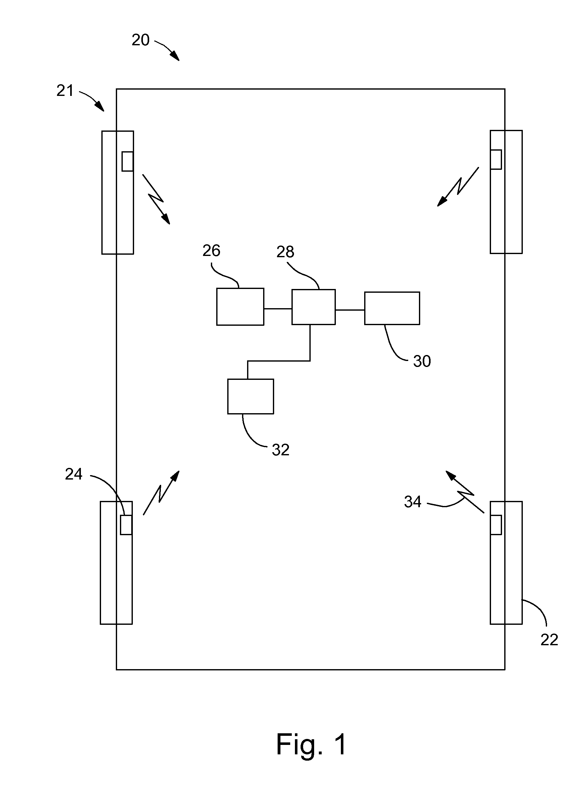
[0009]Referring to FIG. 1, a vehicle, indicated generally at 20, is shown. The vehicle 20 has a tire monitoring system 21 and includes tire and wheel assemblies 22 that each have a tire sensor assembly 24 mounted inside. The tire sensor assemblies 24 each transmit signals 34 to a tire sensor receiver 26. The tire sensor receiver 26 communicates with a controller 28. The controller 28 may be any one or more of various controllers employed with vehicles and may be made up of various combinations of hardware and software as is known to those skilled in the art. For example, the controller 28 may be a chassis controller—although it may include one or more different vehicle controllers. The controller 28 may communicate with one or more vehicle systems 30. The vehicle systems 30 may include, for example, anti-lock brake systems, traction control systems, stability control systems, or other types of vehicle systems. These systems are known to those skilled in the art and so will not be di...


PUM


Abstract

A vehicle tire monitoring system including a tire and wheel assembly. The tire and wheel assembly may include a wheel having a rim portion including an inside surface; a tire including a tire carcass having an inner surface and an outer surface with a tire tread over a radially outer portion of the outer surface, and with the inner surface and the inside surface of the rim portion forming a cavity in which pressurized air is sealed; and a tire sensor assembly mounted on the inside surface of the rim portion in the cavity and including an infrared sensor and a wireless transmitter operatively engaging the infrared sensor, with the infrared sensor oriented to detect a temperature on the inner surface of the tire carcass at a location opposite to a portion of the tire tread.

Description

BACKGROUND OF INVENTION[0001]The present invention relates generally to tire monitors and temperature sensors used with vehicle tires.[0002]It may be desirable in tire pressure measurement systems to accurately measure the tire tread temperature. Some have measured the temperature of the air inside the tire to estimate the tire tread temperature. However, this is a slow changing measurement relative to the tire tread temperature and does not necessarily accurately reflect the tire tread temperature for various vehicle operating conditions. Others use a thermocouple and slip ring, but these types of arrangements may not be as durable as desired and may be more costly than is desired for a vehicle. Still others employ exterior mounted infrared sensors directed toward the tire tread, but these sensors can become dirty relatively quickly, which may cause them to stop working. Some have employed tire temperature modeling to estimate the tire tread temperature, but this may not be as accu...

Claims


Application Information

Patent Timeline
Patent Type & Authority Applications(United States)
IPC IPC(8): G01J5/02G08B21/18
CPCB60C23/20B60C23/0498
Inventor SIMMERMAN, CRAIG T.GRUTTA, ANTHONY D.TRZCINSKI, DAVID J.WIESE, RICHARD W.
Owner GM GLOBAL TECH OPERATIONS LLC
Why Eureka
Try Eureka