Touch panel

a touch panel and touch technology, applied in the field of touch panels, can solve the problems of reducing the touch sensitivity at the edges of the active region, increasing the size of the touch panel, and unable to effectively drive products using the keyboard and the mouse, so as to achieve the effect of improving the touch sensitivity

Inactive Publication Date: 2013-12-26
SAMSUNG ELECTRO MECHANICS CO LTD
View PDF6 Cites 5 Cited by
  • Summary
  • Abstract
  • Description
  • Claims
  • Application Information

AI Technical Summary

Benefits of technology

[0016]The present invention has been made in an effort to provide a touch panel in which touch sensitivity may be improved at edges of an active region of the touch panel even though an electrode is not formed to extend to an inactive region.

Problems solved by technology

However, since the use of the computer has gradually widened with the rapid progress of an information society, there are difficulties in effectively driving products only using the keyboard and the mouse currently acting as an input device.
For this reason, the conventional touch panel has a problem in that touch sensitivity at the edges of the active region is reduced.
However, in this case, the touch panel has a problem in that a size of the touch panel is increased due to extension of the inactive region, or the active region which is visually recognizable in the touch panel having a fixed size has to be reduced.

Method used


Image

  • Touch panel
  • Touch panel
  • Touch panel

Examples


second embodiment

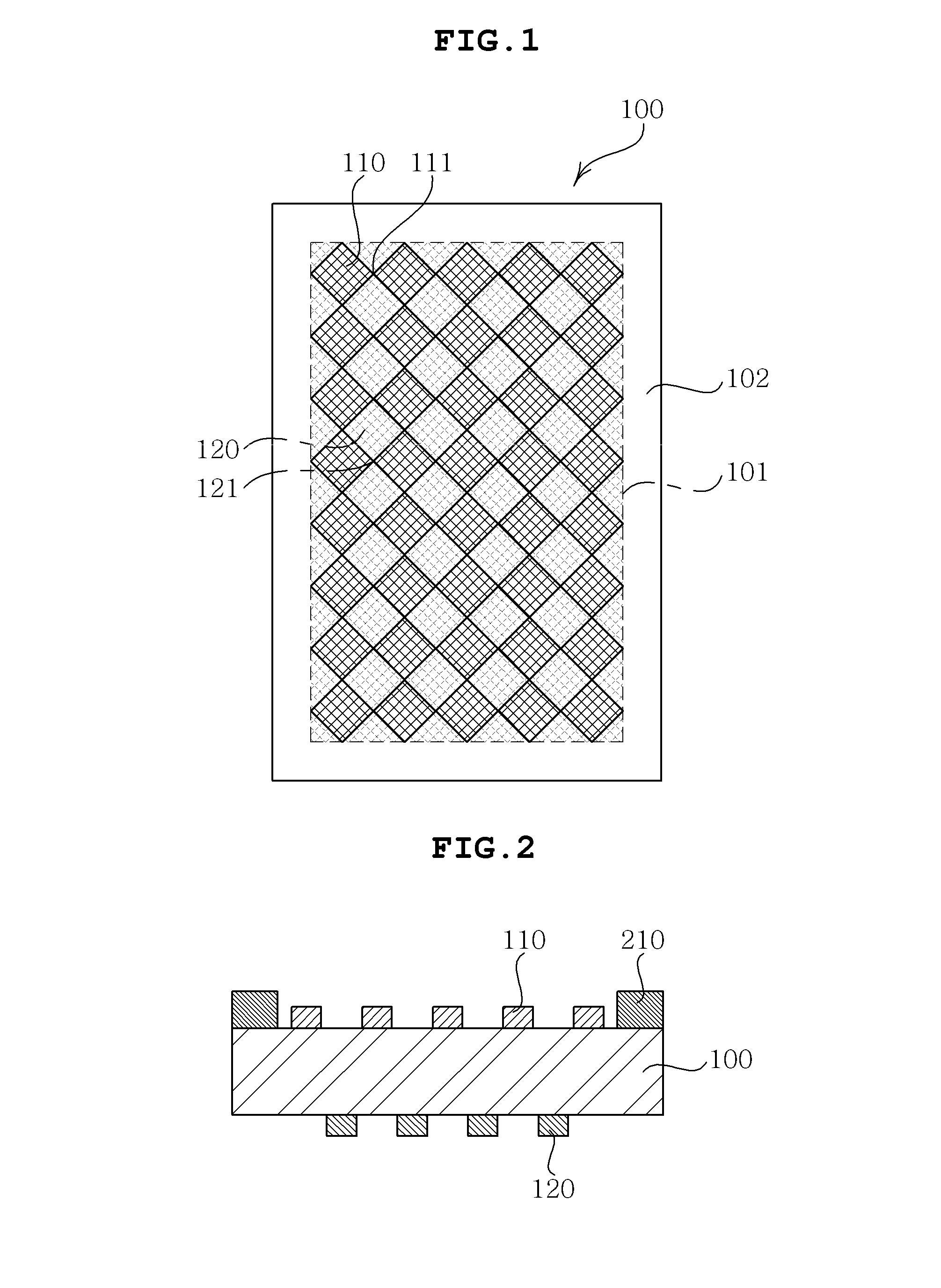
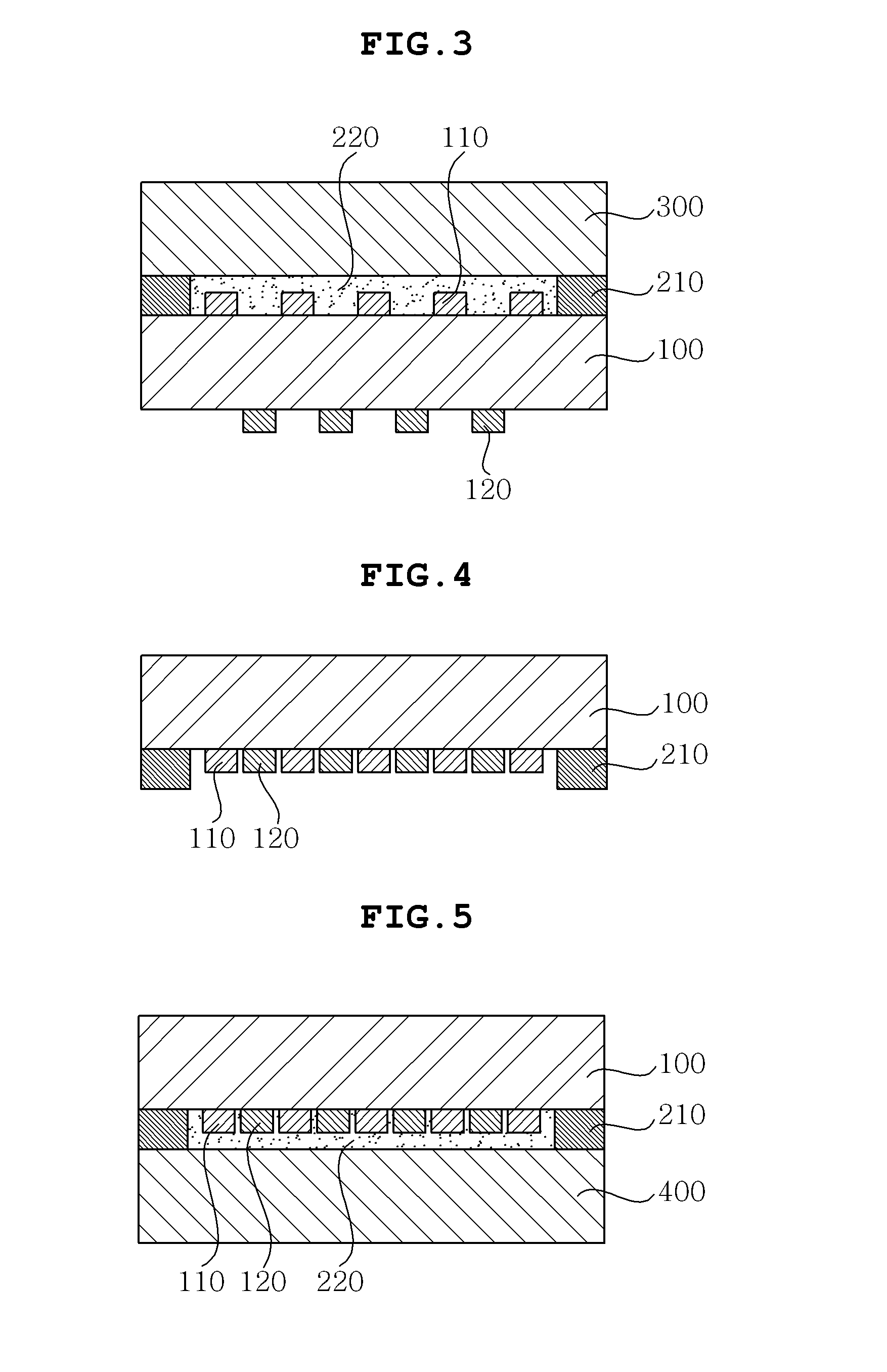
[0067]FIGS. 4 and 5 are cross-sectional views of a touch panel according to the present invention.

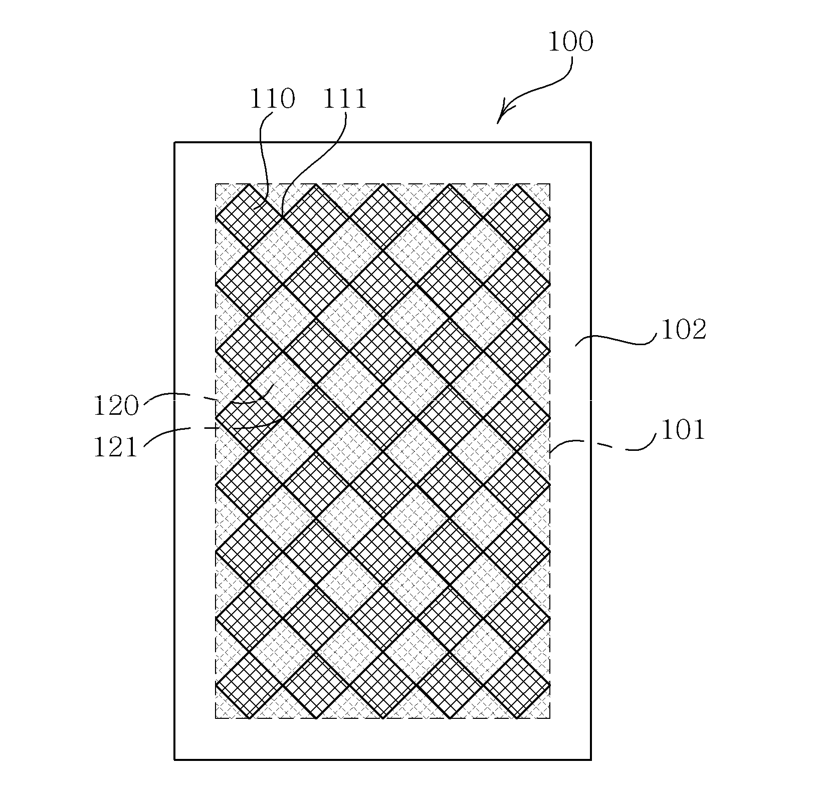
[0068]As shown in FIG. 4, according to the present embodiment, a transparent substrate 100 that is partitioned into an active region 101 (see, FIG. 1) and an inactive region 102 (see, FIG. 1) outside the active region 101, first and second electrodes 110 and 120 that are formed in the active region 101 of one surface of the transparent substrate 100, and a low dielectric constant film 210 that is formed along a peripheral edge of the active region 101 while being formed in the inactive region 102 of the one surface of the transparent surface 100.

[0069]The transparent substrate 100 according to the second embodiment may be the window glass 300 described in the first embodiment. In this case, according to the present embodiment, a separate substrate which is attached to the window glass is not required. Both the first electrode 110 and the second electrode 120 are formed on the one surfac...

first embodiment

[0070]The first electrode 110 may be formed in a diamond pattern which is arranged in a first direction and a bridge pattern which connects the diamond pattern as described in the The second electrode 120 may be formed in a diamond pattern which is arranged in a second direction and a bridge pattern which connects the diamond pattern while being formed on a remaining region except a region where the diamond pattern of the first electrode 110 is formed. In this instance, although not shown, in a region which intersects each other between the bridge pattern of the first electrode 110 and the bridge pattern of the second electrode 120, an insulating layer may be formed between the bridge patterns for the purpose of insulating between the bridge patterns.

[0071]In addition, according to the present embodiment, as described in the first embodiment, the low dielectric constant film 210 is formed on the inactive region 102 along a peripheral edge of the active region 101 of the one surface...


PUM


Abstract

Disclosed herein is a touch panel. The touch panel according to a first embodiment of the present invention includes a transparent substrate that is partitioned into an active region and an inactive region outside the active region, a first electrode that is formed in the active region of one surface of the transparent substrate, a second electrode that is formed in the active region of the other surface of the transparent substrate, and a low dielectric constant film that is formed along a peripheral edge of the active region while being formed in the inactive region of the one surface of the transparent substrate. In the touch panel, touch sensitivity is improved by minimizing influence of a polarization phenomenon on changes in capacitance on the peripheral edge of the active region in which a detection region is reduced.

Description

CROSS REFERENCE TO RELATED APPLICATION[0001]This application claims the benefit of Korean Patent Application No. 10-2012-0067438, filed on Jun. 22, 2012, entitled “Touch Panel”, which is hereby incorporated by reference in its entirety into this application.BACKGROUND OF THE INVENTION[0002]1. Technical Field[0003]The present invention relates to a touch panel.[0004]2. Description of the Related Art[0005]With the development of computers using digital technology, computer assisted devices have been developed, and personal computers, portable transmission devices, information processing devices exclusive for individual, and the like perform a text and graphic process using a variety of input devices such as a keyboard, a mouse, and the like.[0006]However, since the use of the computer has gradually widened with the rapid progress of an information society, there are difficulties in effectively driving products only using the keyboard and the mouse currently acting as an input device. ...

Claims


Application Information

Patent Timeline
Patent Type & Authority Applications(United States)
IPC IPC(8): G06F3/041
CPCG06F2203/04103G06F3/0445G06F3/0443G06F3/044G06F3/041
Inventor LEE, SEUNG MINOH, SANG HWANPARK, HO JOONLEE, WAN JAC
Owner SAMSUNG ELECTRO MECHANICS CO LTD
Why Eureka
Try Eureka