Imaging apparatus
a technology of imaging apparatus and spherical tube, which is applied in the direction of color signal processing circuit, color television details, television system, etc., can solve the problems of not being able to obtain the image desired by the user, flicker cannot be prevented by the foregoing various techniques, and image becomes brigh
- Summary
- Abstract
- Description
- Claims
- Application Information
AI Technical Summary
Benefits of technology
Problems solved by technology
Method used
Image

Examples
first embodiment
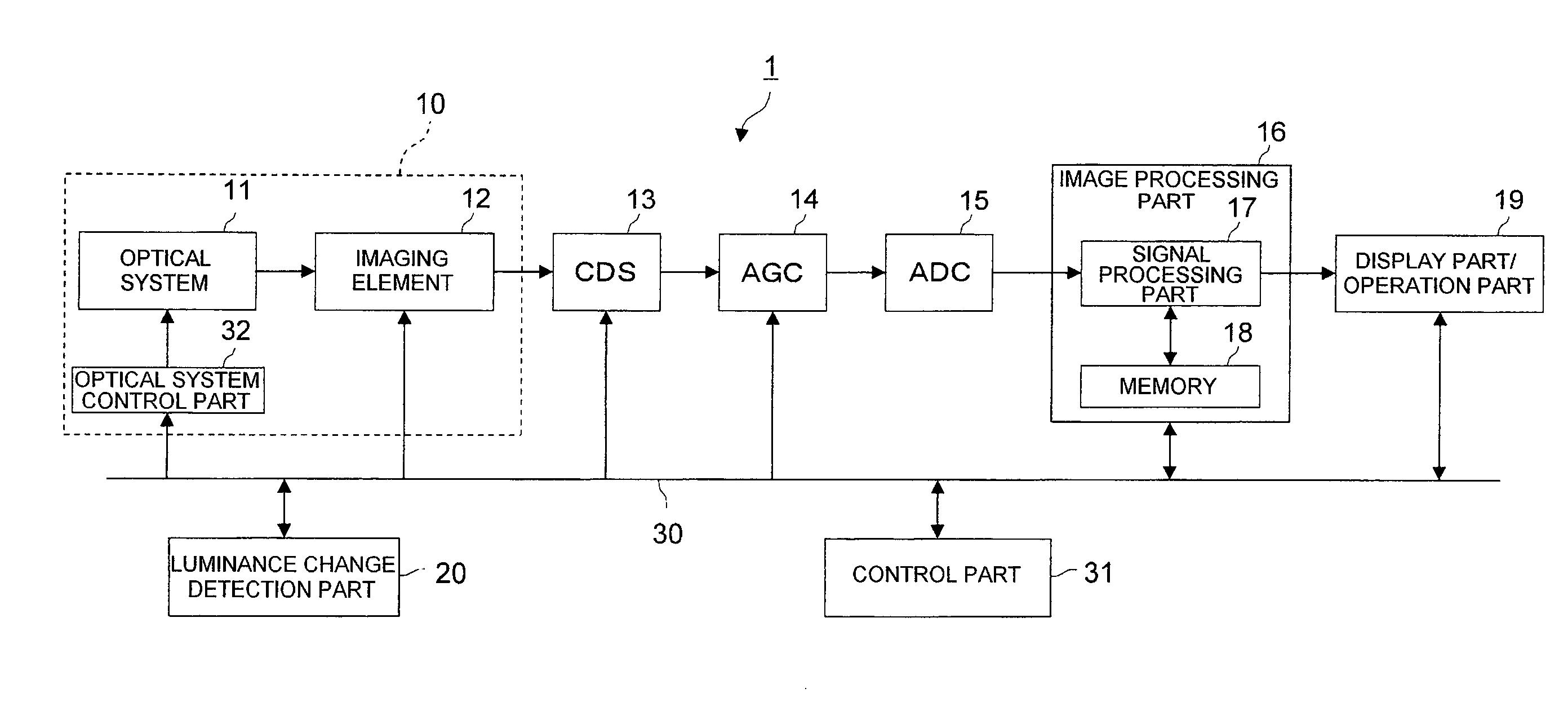
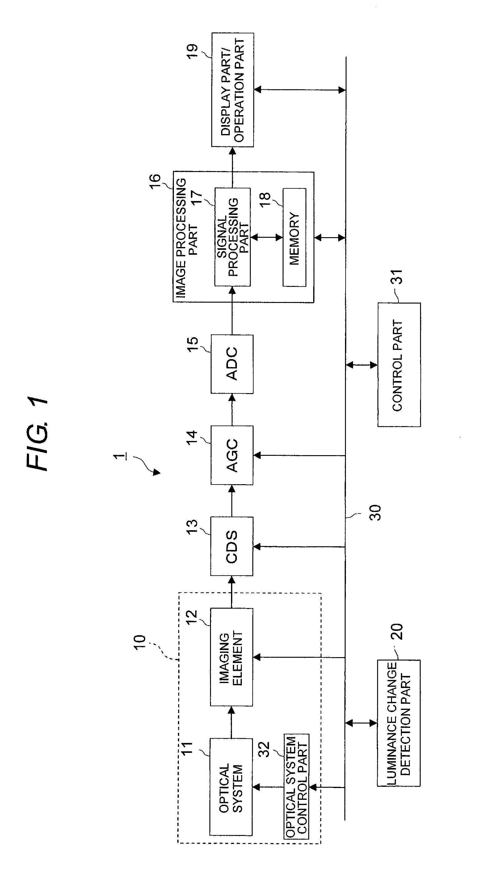
[0022]FIG. 1 is a structural view of an imaging apparatus of a first embodiment of the invention. In the drawing, the imaging apparatus 1 of this embodiment includes an imaging part 10 that includes an optical system 11, an imaging element 12 and an optical control part 32, a CDS 13, an analog AGC 14, an ADC 15, an image processing part 16, a display part / operation part (user interface unit) 19, a luminance change detection part 20 and a control part 31.
[0023]The optical system 11 includes a lens system that includes an imaging lens and the like and forms a subject image, a mechanical diaphragm mechanism (mechanical iris) and a mechanical shutter mechanism (mechanical shutter). The optical control part 32 controls the optical system 11 according to a control instruction of the control part 31. The optical control part 32 includes a lens control part to control the lens system, an iris control part to control the mechanical iris, and a shutter control part to control the mechanical s...
second embodiment
[0075]Next, an imaging apparatus of a second embodiment of the invention will be described. The structure of the imaging apparatus of this embodiment is similar to that of the first embodiment (FIG. 1), and is different only in a gain control system of an analog AGC 14 by a control part 31. Accordingly, the respective components are denoted by the same reference numerals as those of the first embodiment (FIG. 1).
[0076]As described in the first embodiment, the analog AGC 14 is an automatic gain control unit, and adjusts the signal level of an analog imaging signal from the CDS 13 to a specified level based on the instruction of the control part 31. By this, even if the amount of incident light is changed, automatic gain adjustment to a constant level can be performed by automatically correcting the intensity of the image signal level, and the brightness of the output image can be made constant.
[0077]In the imaging apparatus of this embodiment, similarly to the first embodiment, the c...
third embodiment
[0095]Next, an imaging apparatus of a third embodiment of the invention will be described with reference to FIG. 6. Here, FIG. 6 is a structural view of the imaging apparatus of the third embodiment. In the drawing, the imaging apparatus 2 of this embodiment includes an imaging part 10 including an optical system 11, an imaging element 12 and an optical control part 32, a CDS 13, an ADC 15a, an image processing part 16a, a display part / operation part (user interface unit) 19, a luminance change detection part 20 and a control part 31a. Here, the same components as those of the first embodiment are denoted by the same reference numerals and a description thereof is omitted, and like components are denoted by adding “a” to the same reference numerals.
[0096]The image processing part 16a includes a signal processing part (signal processing unit) 17a and a memory 18a, and performs various signal processes on an image signal which is subjected to an analog signal processing through AFE (t...
PUM
 Abstract
Description
Claims
Application Information
 - Generate Ideas
- Intellectual Property
- Life Sciences
- Materials
- Tech Scout
- Unparalleled Data Quality
- Higher Quality Content
- 60% Fewer Hallucinations
Browse by: Latest US Patents, China's latest patents, Technical Efficacy Thesaurus, Application Domain, Technology Topic, Popular Technical Reports.
© 2025 PatSnap. All rights reserved.Legal|Privacy policy|Modern Slavery Act Transparency Statement|Sitemap|About US| Contact US: help@patsnap.com