Light-exposure device

Active Publication Date: 2013-12-26
V TECH CO LTD
View PDF5 Cites 8 Cited by
  • Summary
  • Abstract
  • Description
  • Claims
  • Application Information

AI Technical Summary

Benefits of technology

[0020]According to the present invention, an exposure pattern of a mask is exposed on the surface of a substrate as an upright equal-magnification image, and pulsed exposure is iterated while moving the substrate, whereby all regions to be exposed on the substrate are exposed; and another region of the exposure pattern of the mask is then exposed while moving the substrate shifting the positional relationship between the microlens array and the mask by

Problems solved by technology

However, when the substrate used is small, for example, such as a glass substrate used in a liquid crystal display, or the like, for a portable tele

Method used


Image

  • Light-exposure device
  • Light-exposure device
  • Light-exposure device

Examples


second embodiment

[0076]In the present embodiment as well, the exposure cycle time can be appreciably improved in exposure of the second or further layer by changing the movement speed of the stage 10 and the substrate 2 as needed in the same manner as in the

fourth embodiment

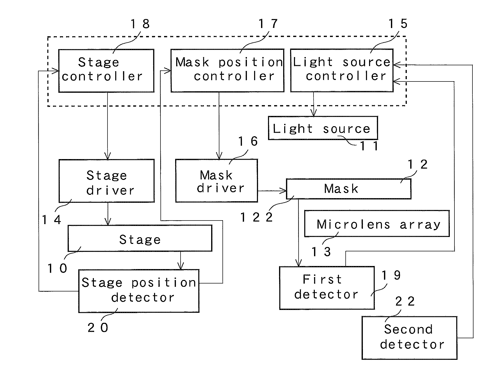
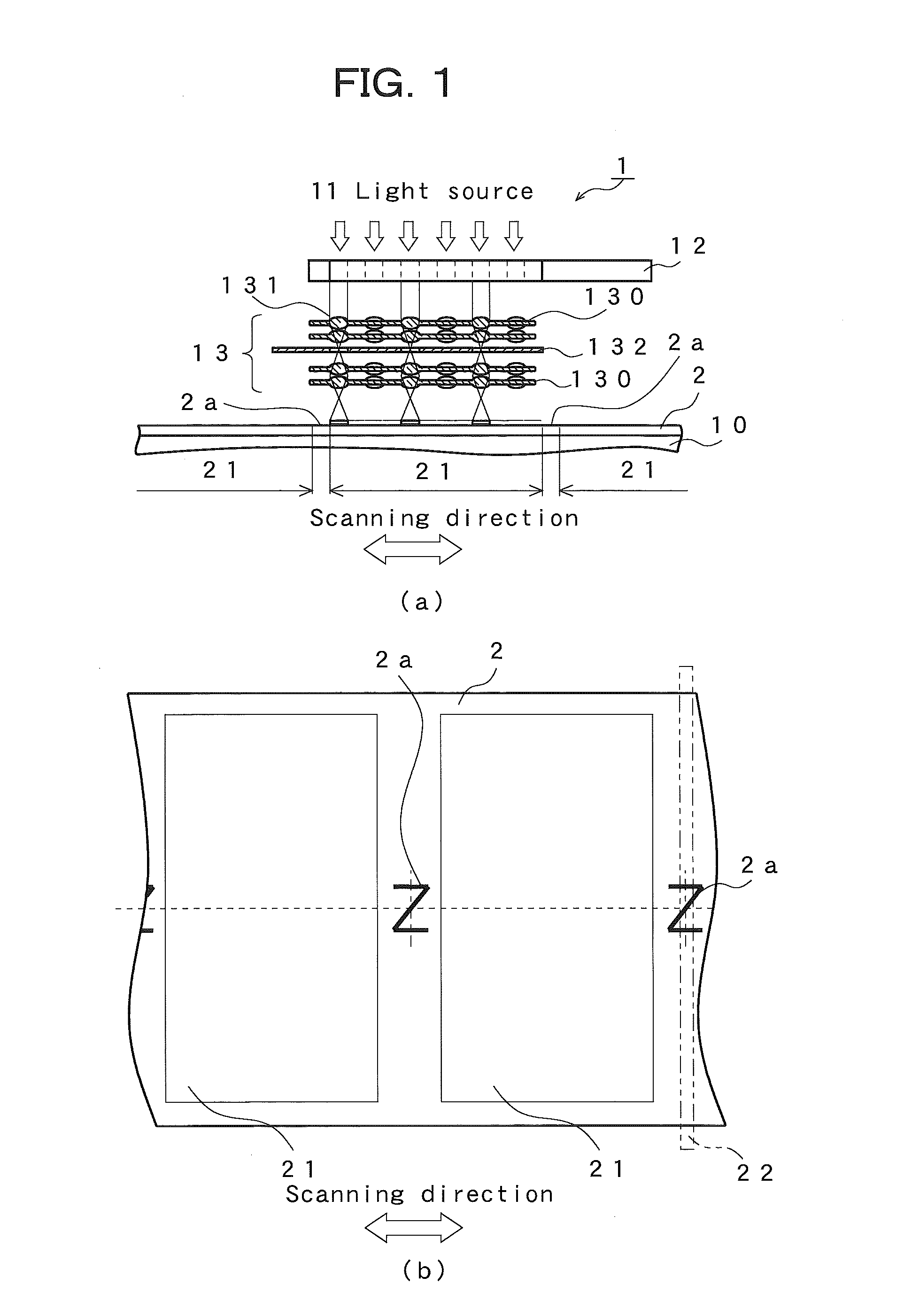
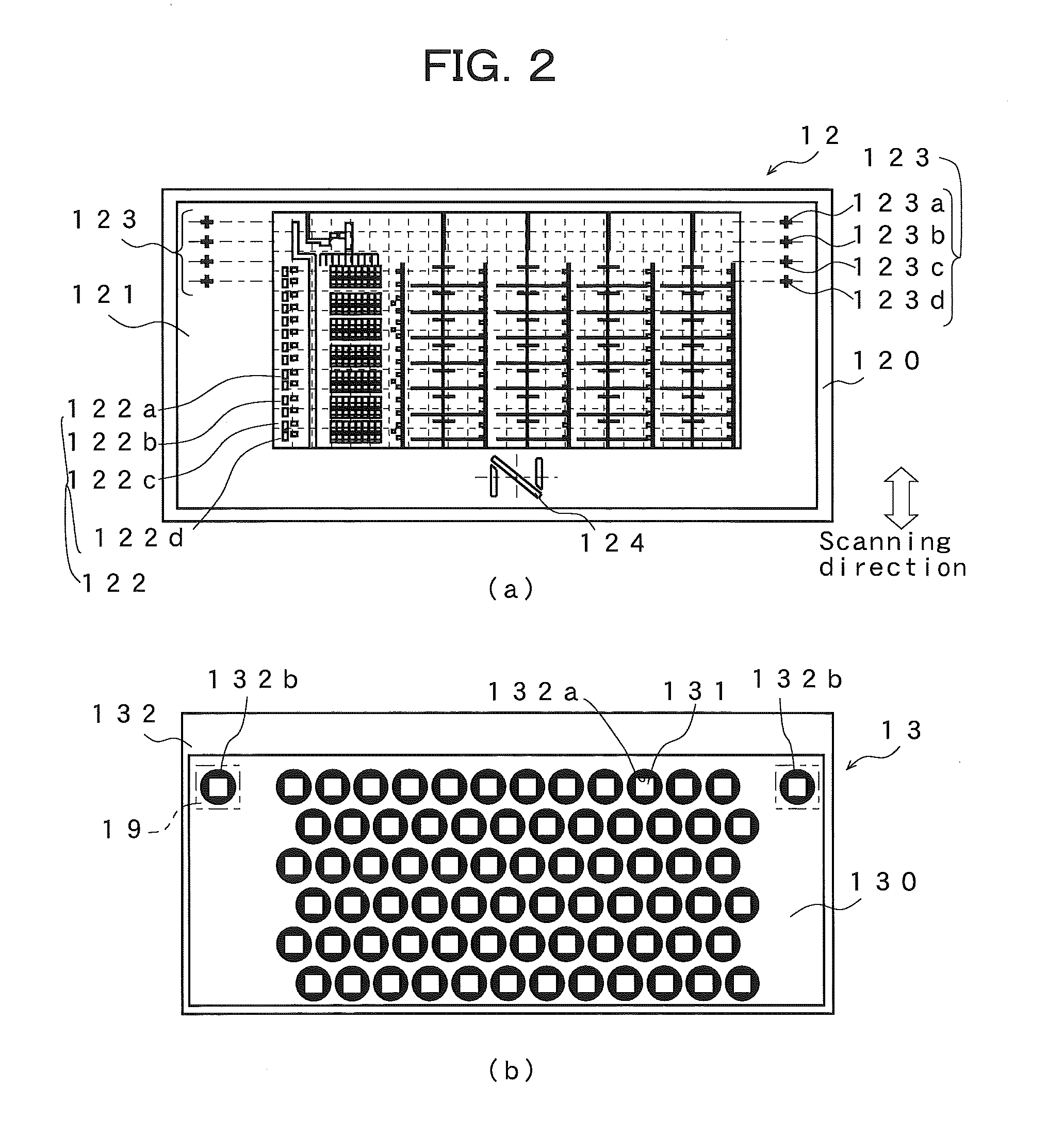
[0077]The light-exposure device according to the present invention is next described. In the present embodiment, the configuration in the light-exposure device illustrated in FIG. 14 is such that a line CCD or other detector 22 extending in the first direction is capable of detecting also a position in the first direction with respect to N-shaped marks 2a provided corresponding respectively to the regions 21 to become individual substrates. That is, in the present embodiment, the detector 22 detects the position of the regions 21 to become individual substrates in the first direction by detecting the center position between the two sides extending in the second direction of the mark 2a. Likewise, the configuration is such that the detector 22 is capable of detecting the center position in the first direction also with respect to the N-shaped slits 124 in the mask 12a. The configuration is such that when forming a pattern of a second or further layer, for example, when the position o...


PUM


Abstract

A light-exposure device is provided with a microlens array on which is arranged with a prescribed regularity a plurality of microlenses on which exposure light transmitted through a light source and a mask is introduced to resolve an upright equal-magnification image on a substrate. Upon reaching a prescribed position, the substrate is irradiated with pulsed laser light from the light source, and the substrate is successively exposed, and after the entire area of the exposure region of the substrate is exposed, a relative positional relationship between the microlens array and the mask is successively switched in a vertical direction by an amount of a horizontal pitch of the microlenses, and a subsequent exposure is performed. Exposure with high precision and high resolution can thereby be performed with a short exposure cycle time.

Description

TECHNICAL FIELD[0001]The present invention relates to a light-exposure device for exposing glass substrates, or the like, used in liquid crystal display panels, or the like, for mobile telephones, and relates more specifically to a stepper-type light-exposure device for batch-exposing a substrate on which is formed a plurality of regions to become individual substrates, irradiating the substrate with exposure light in a region to become one or a plurality of individual substrates while moving the substrate in one direction.BACKGROUND ART[0002]Lens-scanning-type, mirror-projection-type, proximity-type, and other types of light-exposure devices are conventionally used, for example, for exposure of glass substrates, or the like, used in large liquid crystal display panels, or the like. Another practice is to introduce light transmitted through a pattern formed on a large mask into a plurality of projection optical systems (multi-lens), resolve images separately on a substrate, and expo...

Claims


Application Information

Patent Timeline
IPC IPC(8): G03F7/20
CPCG03F7/70191G02B3/0056G03F7/70275G03F7/70358G03F7/20G03F7/70216
Inventor KAJIYAMA, KOICHIMIZUMURA, MICHINOBUHATANAKA, MAKOTO
Owner V TECH CO LTD
Why Eureka
Try Eureka