Medical magnification device

Inactive Publication Date: 2013-12-26
JURKAT KLAUS PETER
View PDF3 Cites 0 Cited by
  • Summary
  • Abstract
  • Description
  • Claims
  • Application Information

AI Technical Summary

Benefits of technology

[0023]The solution according to the invention thus has several advantages with respect to examining tight and deep cavities, for example tooth cavities which so far have only been feasible with stereo microscopes that had complex configurations and operations and where cost intensive to produce. The instant devices for visual magnification of objects in particular in the dental field provides the examination of cavities in intermediary spaces between teeth and irregularities of root canals of teeth f

Problems solved by technology

The surgery microscopes have a stronger magnification compared to a magnifying eye glass, however, they require particularly stable positioning and typically very uncomfortable and complex support for the patient.
12.5 mm the optical resolution when viewing with a bare eye is insufficient.
Thus, the objective lens is vertically oriented from the top down and can only be pivoted in lateral direc

Method used


Image

  • Medical magnification device
  • Medical magnification device
  • Medical magnification device

Examples


Embodiment Construction

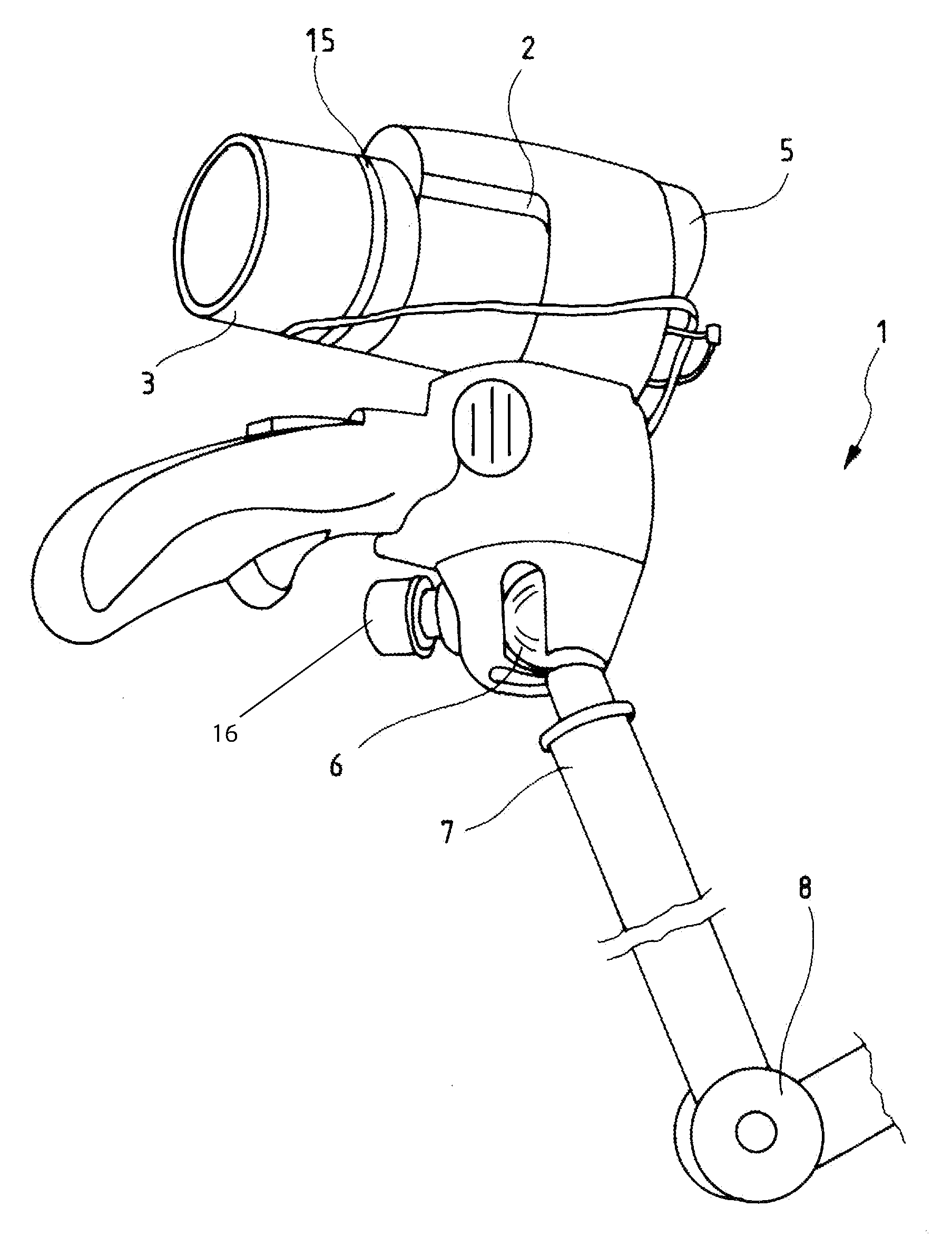
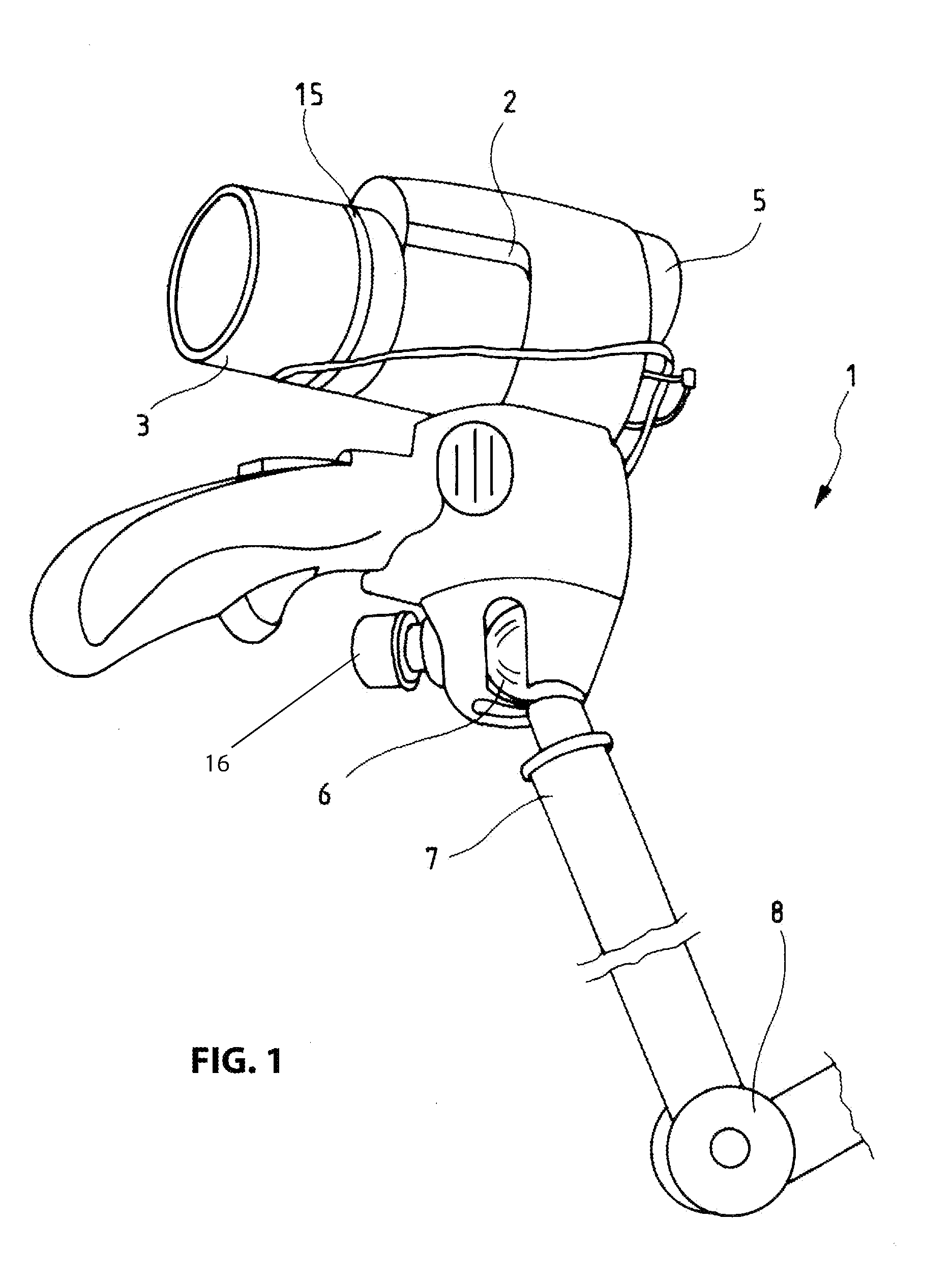
[0029]FIG. 1 illustrates a single eye piece magnification device 1 according to the invention for visual magnification of objects in a lateral view. The optical unit 2 configured as a one tube telescope includes an eye piece 5 at the proximal end, this means at the end oriented toward the viewer. At the distal end, or the end of the optical unit 2 oriented away from the viewer the optical unit 2 is provided with a manually operable focusing device 15 which is configured for focusing for a variable change of a distance between the object to be examined and the optical unit 2 in a range between 20 cm and 40 cm.

[0030]The optical unit 2 in particular the focusing device 15 according to an alternative embodiment is provided with electrically driven actuation motors and electrically connected with a power source. Thus, for example an electrical energy storage device like a battery or the public power grid is being used.

[0031]The optical unit 2 is thus provided for up to 12 power magnifica...


PUM


Abstract

The invention relates to a medical magnification device which has an optical unit with an optical axis, illuminating means and attachment elements, wherein the optical unit has at the proximal end, an eyepiece of monocular design, and the illuminating means is configured in the form of a hollow cylinder, is connected at a distal end to the optical unit and is coaxial with respect to the optical axis generating a concentric illumination pattern and the attachment elements include means that can be connected to the optical unit and that are configured so that the optical unit is adjustable in any direction.

Description

RELATED APPLICATIONS[0001]This application is a continuation of PCT / EP2011 / 059280, filed on Jun. 6, 2011, claiming priority from German Patent Application DE 20 2010 007 662.5, filed on Jun. 7, 2010, both of which are incorporated in their entirety by this reference.FIELD OF THE INVENTION[0002]The invention relates to a device for visual magnification of objects in medical applications, in particular in dentistry, ear nose and throat medicine for diagnosing very small details in small and particularly deep cavities.BACKGROUND OF THE INVENTION[0003]In the field of the invention for example magnifying eye glasses are being used which, however, only provide little magnification. In the art furthermore surgery microscopes are known for the medical field in particular in surgery and micro surgery which are microscopes with approximately 6 power to 40 power magnification. The surgery microscopes have a stronger magnification compared to a magnifying eye glass, however, they require partic...

Claims


Application Information

Patent Timeline
IPC IPC(8): G02B25/02
CPCG02B25/02A61B17/24A61B2090/3616A61B90/20A61C5/40
Inventor JURKAT, KLAUS-PETER
Owner JURKAT KLAUS PETER
Why Eureka
Try Eureka