Vehicle power transmission device

a technology of transmission device and transmission device, which is applied in the direction of gearing details, gearing, transportation and packaging, etc., can solve the problems of noise and vibration, noise and vibration may easily occur, etc., and achieve the suppression of the generation of vibratory force, the reduction of the vibration force transmitted to the case, and the restraint of the reaction force of the meshing

Inactive Publication Date: 2013-12-26
TOYOTA JIDOSHA KK
View PDF2 Cites 21 Cited by
  • Summary
  • Abstract
  • Description
  • Claims
  • Application Information

AI Technical Summary

Benefits of technology

[0010]Consequently, a vibratory force input to the cylindrical output member from the output gear of the cylindrical output member and the second planetary gear device disposed on the inner circumferential side of the cylindrical output member is attenuated by the second carrier before transmission to the case. Therefore, the vibratory force transmitted to the case is made smaller as compared to the case of directly transmitting the vibratory force to the case without passing through the second carrier. A meshing reaction force of the output gear acting on the cylindrical output member is transmitted via the second carrier and a carrier pin to each of a plurality of pinions included in the second planetary gear device. Therefore, the meshing reaction force is restrained from being input from the second ring gear to a portion of the plurality of the pinions in a biased manner, resulting in suppression of the generation of the vibratory force associated with deterioration of tooth contact between the portion of the pinions and the second ring gear. Thus, the vehicle power transmission device is acquired that can suppress the occurrence of noise and vibration.
[0011]Preferably, the bearing is disposed to partially or entirely overlap with the output gear when viewed in a direction orthogonal to the axial center line. Since this suppresses occurrence of misalignment of the cylindrical output member due to the meshing reaction force of the output gear, a portion of the meshing reaction forc

Problems solved by technology

Therefore, since a vibratory force input from the output gear, the second planetary gear device, etc., to the cylindrical output member is directly transmitted to the case, noise and vibration may easily occur.
Therefore, since a portion of a meshing reaction force of the output gear acting on the cylindrical output member is input via the second ring gear of the second planeta

Method used


Image

  • Vehicle power transmission device
  • Vehicle power transmission device
  • Vehicle power transmission device

Examples


first embodiment

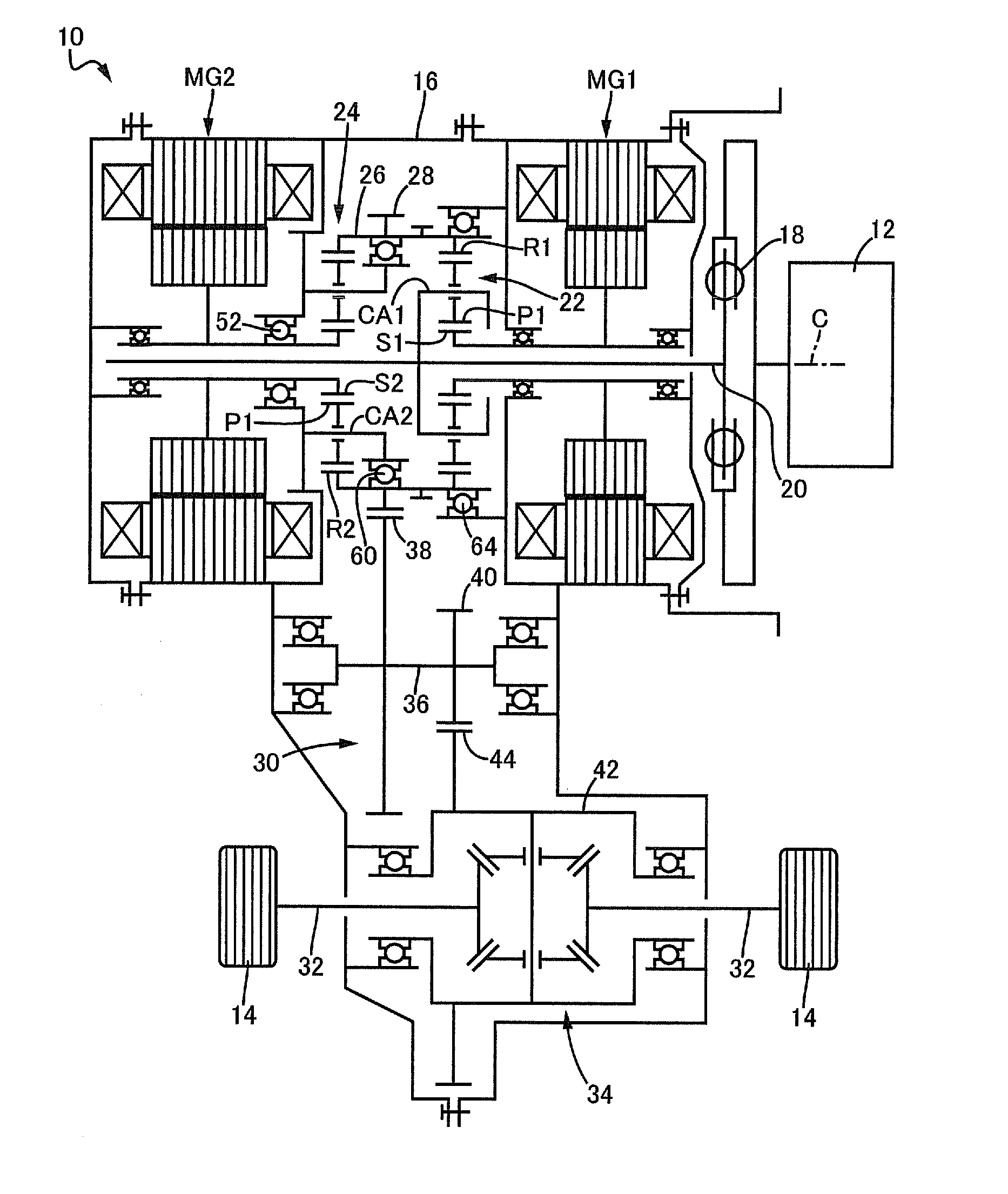
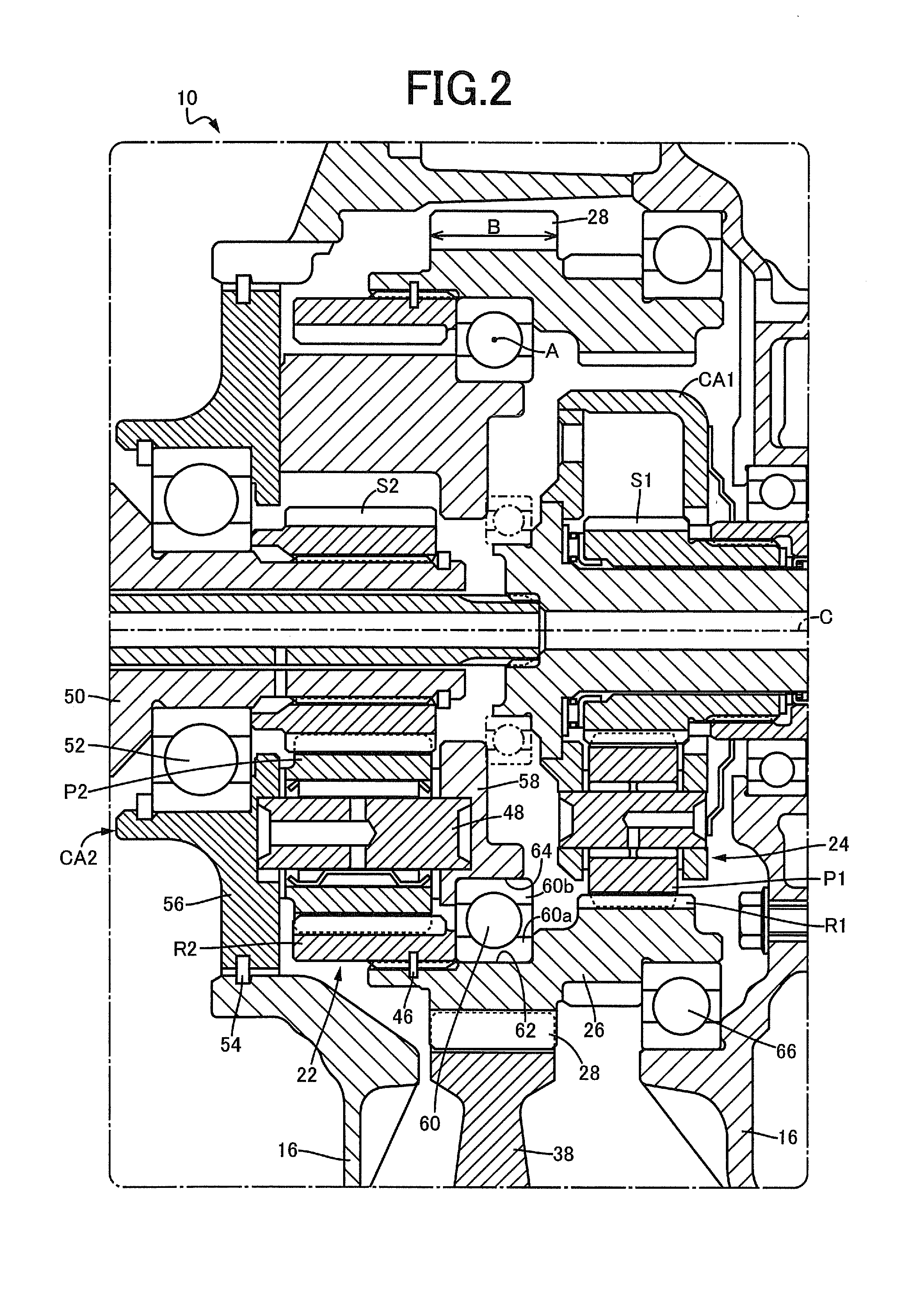
[0021]FIG. 1 is a schematic for explaining a configuration of a vehicle power transmission device 10 of one embodiment of the present invention. In FIG. 1, the power transmission device 10 is disposed on a power transmission path between an engine 12 and drive wheels 14 on a hybrid vehicle of the FF (front-engine front-drive) type, for example. The power transmission device 10 includes, in a transaxle case 16 attached to a vehicle body, a damper 18 absorbing pulsation due to fluctuations of torque from the engine 12, and an input shaft 20 coupled via the damper 18 to the engine 14, as well as a first motor generator MG1, a first planetary gear device 22, a second planetary gear device 24, and a second motor generator MG2 disposed in this order from the damper 18 side on the outer circumferential side of the input shaft 20. The transaxle case 16 corresponds to a case of the present invention. The first motor generator MG1 corresponds to a first electric motor of the present invention...

second embodiment

[0042]Other embodiments of the present invention will be described. In the description of the following embodiments, the portions common to the embodiments are denoted by the same reference numerals and will not be described.

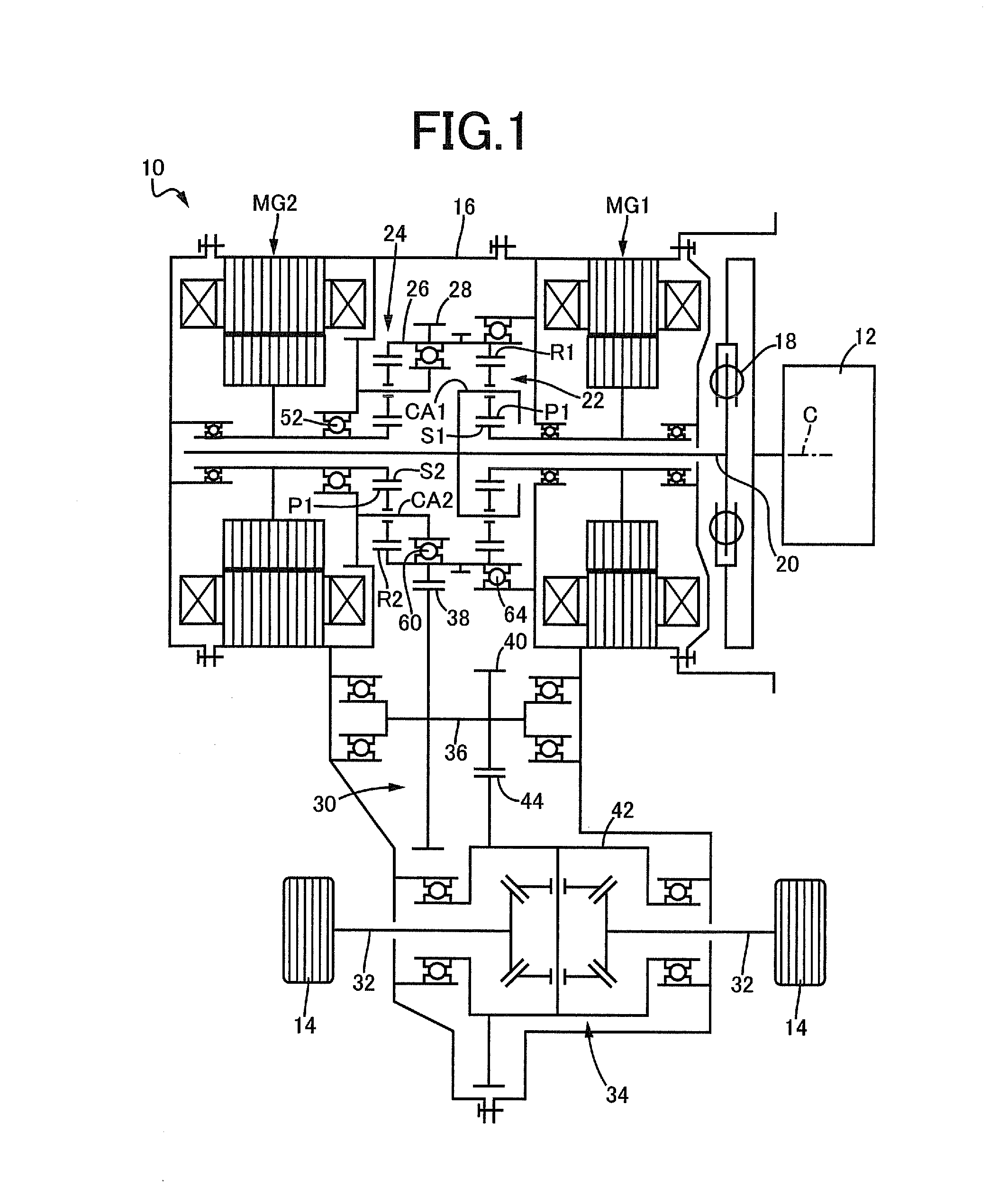
[0043]FIG. 3 is a cross-sectional view of a main portion of a vehicle power transmission device 70 of another embodiment of the present invention, corresponding to FIG. 2 of the first embodiment. As depicted in FIG. 3, in this embodiment, the second bearing 60 of the first embodiment is replaced with a second bearing 72 that is a cylindrical roller bearing. The second bearing 72 corresponds to the bearing of the present invention and is disposed between the first ring gear R1 and the second ring gear R2 on the inner circumferential side of a cylindrical output member 74 of this embodiment. The cylindrical output member 74 is rotatably supported by the second carrier member 58 of the second carrier CA fixed to the transaxle case 16, via the second bearing 72 disp...

third embodiment

[0051]FIG. 4 is a cross-sectional view of a main portion of a vehicle power transmission device 80 of another embodiment of the present invention, corresponding to FIG. 2 of the first embodiment. As depicted in FIG. 4, in this embodiment, the second bearing 60 of the first embodiment is replaced with a second bearing 82 that is a double row ball bearing. The second bearing 82 corresponds to the bearing of the present invention and is disposed between the first ring gear R1 and the second ring gear R2 on the inner circumferential side of a cylindrical output member 84 of this embodiment. The cylindrical output member 84 is rotatably supported by the second carrier member 58 of the second carrier CA fixed to the transaxle case 16, via the second bearing 82 disposed to entirely overlap with the first drive gear 28 when viewed in the direction orthogonal to the axial center line C on the inner circumferential side of the cylindrical output member 84.

[0052]The second bearing 82 is positi...


PUM


Abstract

A vehicle power transmission device includes: a first planetary gear device distributing power from an engine to a first electric motor and a cylindrical output member having an output gear disposed on a portion in an axial center line direction on an outer circumferential side; and a second planetary gear device having a second sun gear coupled to a second electric motor, a second carrier fixed to a case, and a second ring gear coupled to an inner circumference of the cylindrical output member to reduce and transmit output rotation of the second electric motor to the cylindrical output member, the cylindrical output member being supported via a bearing disposed on an inner circumferential side of the cylindrical output member by the second carrier fixed to the case.

Description

TECHNICAL FIELD[0001]The present invention relates to a vehicle power transmission device and particularly to a technique for suppressing vibration and noise occurring in the vehicle power transmission device.BACKGROUND ART[0002]A vehicle power transmission device disposed between an engine and drive wheels is known. For example, this corresponds to those described in Patent Documents 1 to 4. Patent documents 1 and 2 describe a vehicle power transmission device including a first planetary gear device distributing power from the engine to a first electric motor and a cylindrical output member having an output gear disposed on a portion in an axial center line direction on the outer circumferential side, and a second planetary gear device having a second sun gear coupled to a second electric motor, a second carrier fixed to a case, and a second ring gear coupled to an inner circumference of the cylindrical output member to reduce and transmit output rotation of the second electric mot...

Claims


Application Information

Patent Timeline
IPC IPC(8): F16H3/72
CPCF16H3/724Y10S903/902B60K6/365B60K6/405B60K6/445F16H57/021F16H2037/0866F16H2057/02034F16H3/727Y02T10/62
Inventor IWASA, TOMOATSU
Owner TOYOTA JIDOSHA KK
Why Eureka
Try Eureka