Pneumatic motor

a pneumatic motor and rotor technology, applied in the direction of valve arrangement, sealing arrangement of engines, machines/engines, etc., can solve the problems of increased vibration of the motor, reduced stability, and conventional pneumatic motors that don't have sufficient power output stability, etc., to achieve stabler and larger torque output

Inactive Publication Date: 2014-01-02
HYPHONE MASCH IND CO LTD
View PDF9 Cites 1 Cited by
  • Summary
  • Abstract
  • Description
  • Claims
  • Application Information

AI Technical Summary

Benefits of technology

[0009]The main object of the present invention is to provide a pn...

Problems solved by technology

However, conventional pneumatic motors don't have sufficient stability of power output.
When the rotor is driven to rotate by compressed air, entering and releasing of compressed air result that torque the rotor acquires varies to reduce stability, and vibration of the motor...

Method used


Image

  • Pneumatic motor
  • Pneumatic motor
  • Pneumatic motor

Examples


Embodiment Construction

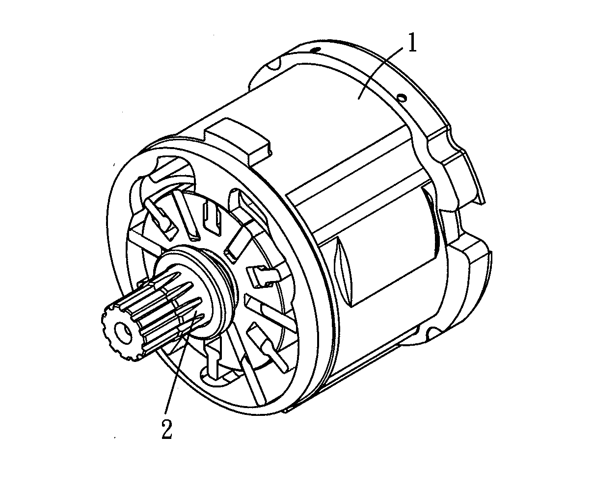
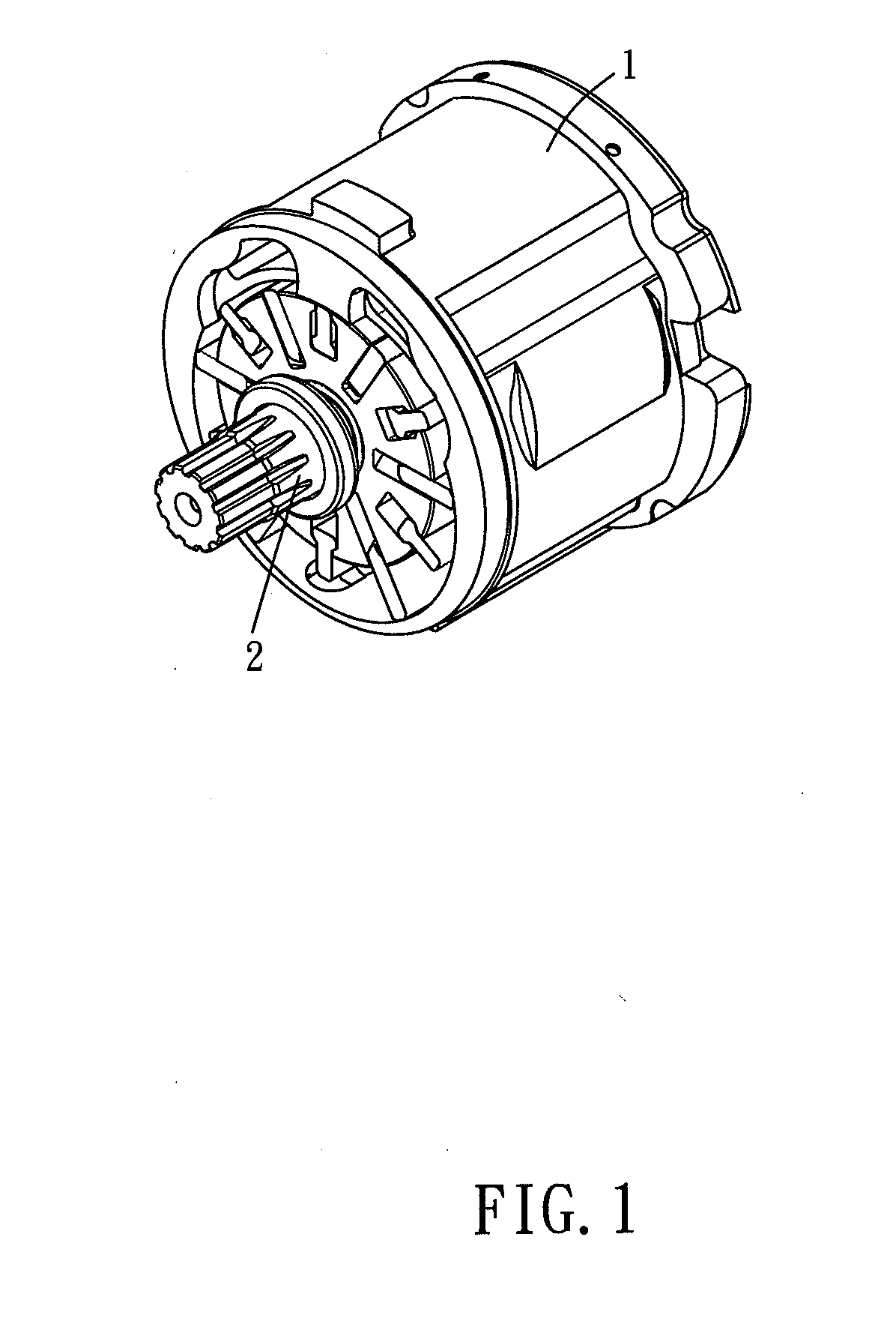
[0023]Please refer to FIG. 1 and FIG. 2 for a major embodiment of the present invention. The pneumatic motor of the present invention is adapted for being installed in pneumatic tools and for being driven by compressed air. The pneumatic motor of the present embodiment includes a cylinder 1, a rotor 2, and a limitation mechanism.

[0024]The cylinder 1 encloses a receiving room 11, an inlet 12, and an outlet 12, wherein the inlet 12 and the outlet 13 communicate with the receiving room 11. The cylinder 1 has an inner wall defined on a circumference of the receiving room 11. Compressed air is able to enter the receiving room 11 via the inlet 12 and then to be discharged via the outlet 13. In other possible embodiment, the cylinder 1 can form a plurality of inlets and outlets, and path of compressed air is able to be changed by a valve. Thus, operating direction of the motor can be changed.

[0025]The rotor 2 includes an axle 21 and a plurality of main blades 22. An axial direction and a r...


PUM


Abstract

A pneumatic motor includes a cylinder and a rotor disposed in the cylinder. The rotor includes an axle, and main and secondary blades are slidably received in a plurality of main and secondary sliding slots formed on the axle. The secondary blades touch an inner wall of the cylinder to promote torque output when located at angles equal to or smaller than a specific angle from an inlet of the cylinder. On the contrary, the secondary blades are away from the inner wall of the cylinder to reduce friction between the rotor and the cylinder when located at angles larger than the specific angle from the inlet. Thus, revolution speed of the rotor is retained in a tolerant range, and torque output is promoted significantly.

Description

BACKGROUND OF THE INVENTION[0001]1. Field of the Invention[0002]The present invention relates to a pneumatic motor, more particularly to a rotor of a pneumatic motor.[0003]2. Description of the Prior Art[0004]A pneumatic motor is driven by compressed air to provide torque output to drive other tools to rotate further. A conventional pneumatic motor usually has adjustment mechanism to increase power output. For example, a pneumatic motor disclosed in patent TW 1259865 has two sets of inlet and outlet, and the motor also includes a control valve assembly to alternatively open or close the inlet and the outlet. Thus, power stoke of compressed air in the motor is increased, and larger torque output is provided.[0005]However, conventional pneumatic motors don't have sufficient stability of power output. Please refer to a pneumatic motor disclosed in patent TW M388576, the rotor disposes only three blades. When the rotor is driven to rotate by compressed air, entering and releasing of com...

Claims


Application Information

Patent Timeline
IPC IPC(8): F01C1/02
CPCF01C1/3442F01C19/02F01C21/0809
Inventor TING, CHIH-MING
Owner HYPHONE MASCH IND CO LTD
Why Eureka
Try Eureka