Parallel state-based controller for a welding power supply

Active Publication Date: 2014-01-02
LINCOLN GLOBAL INC
View PDF7 Cites 45 Cited by
  • Summary
  • Abstract
  • Description
  • Claims
  • Application Information

AI Technical Summary

Benefits of technology

[0006]In accordance with one aspect of the present invention, provided is an arc welding system. The arc welding system includes a welding torch. An electrode is operatively connected to the welding torch, and receives electrical energy from the welding torch. The electrode establishes an electrical arc from the arc welding system. A welding power supply supplies electrical energy for generating the electrical arc according to a welding waveform. The welding power supply comprises a switching type power converter. The switching type power converter is operatively connected to the welding torch for supplying the electrical energy to the welding torch. A parallel state-based controller is operatively connected to the switching type power converter and provides a waveform control signal to the switching type power converter for controlling operations of the switching type power converter. The parallel state-based controller generates a motion control signal for controlling movements of at least one of the electrode and the welding torch. The parallel state-based controller comprises a processor. A sensor, having an output operatively connected to the parallel state-based controller, senses at least one of a welding voltage and a welding current. A memory portion is operatively connected to the processor and stores a welding state table comprising a first plurality of sequential control states, and a motion control system state table comprising a second plurality of sequential control states. The welding waveform is defined in the welding state table. The parallel state-based controller controls the operations of the switching type power converter through the waveform control signal according to the welding state table, and simultaneously adjusts the motion control signal according to the motion control system state table. The parallel state-based controller transitions between control states of the welding state table according to a signal received from the sensor, and also transitions between control states of the motion control system state table according to the signal received from the sensor.
[0007]In accordance with another aspect of the present invention, provided is a method for controlling an arc welding system. The method includes the step of providing the arc welding system. The arc welding system includes a welding torch and a welding power supply. The welding power supply includes a switching type power converter operatively connected to the welding torch. A parallel state-based controller includes a welding state table and a motion control system state table. The arc welding system includes a welding voltage sensor and a welding current sensor. An electrical arc is generated between the arc welding system and a workpiece. The parallel state-based controller controls

Problems solved by technology

Further, the separate controllers often require the use of duplic

Method used


Image

  • Parallel state-based controller for a welding power supply
  • Parallel state-based controller for a welding power supply
  • Parallel state-based controller for a welding power supply

Examples


example associations

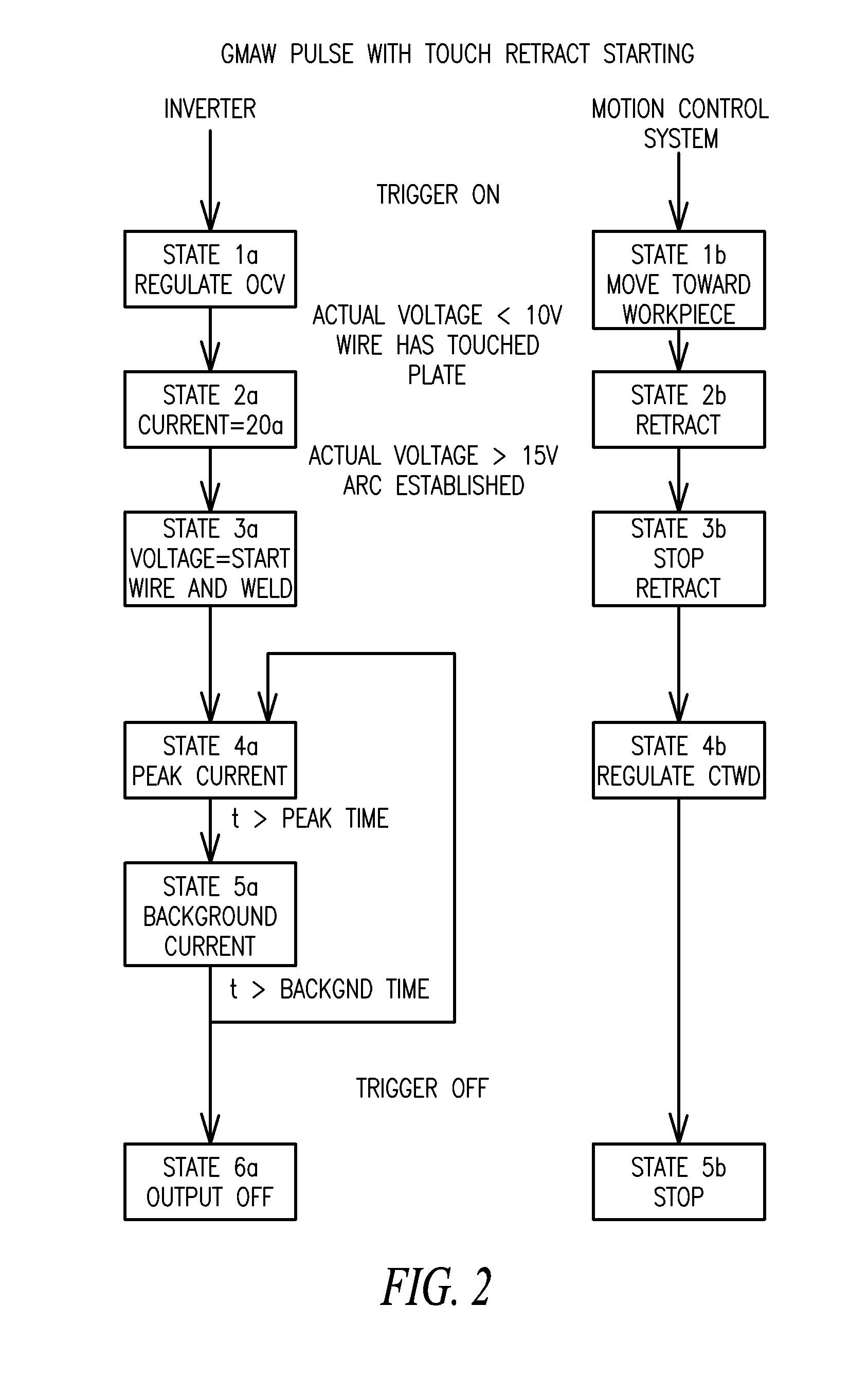
[0045 of the types of welding procedures implemented by different welding state tables and the feedback signals used by respective motion control system state tables to control CTWD are as follows:

Welding Process of Welding State TableConstant Current GTAWConstant Voltage GMAWConstant Current GMAWConstant Current Pulsed GTAWConstant Current Pulsed GMAWAdaptive Pulsed GMAW

Feedback Signal for Regulating CTWDBy Motion Control System State TableAverage VoltageAverage CurrentAverage VoltagePeak VoltagePeak VoltageAverage Power

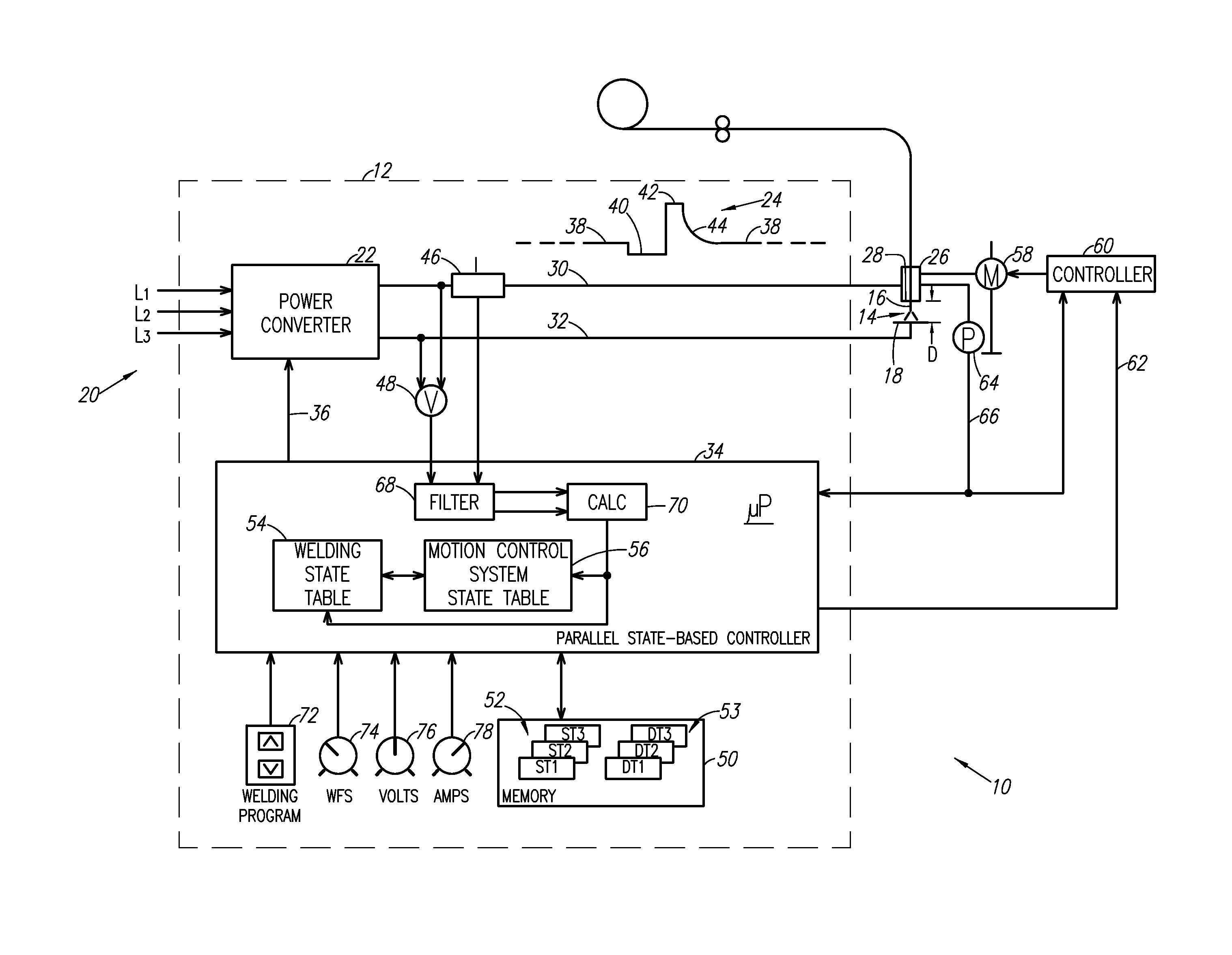
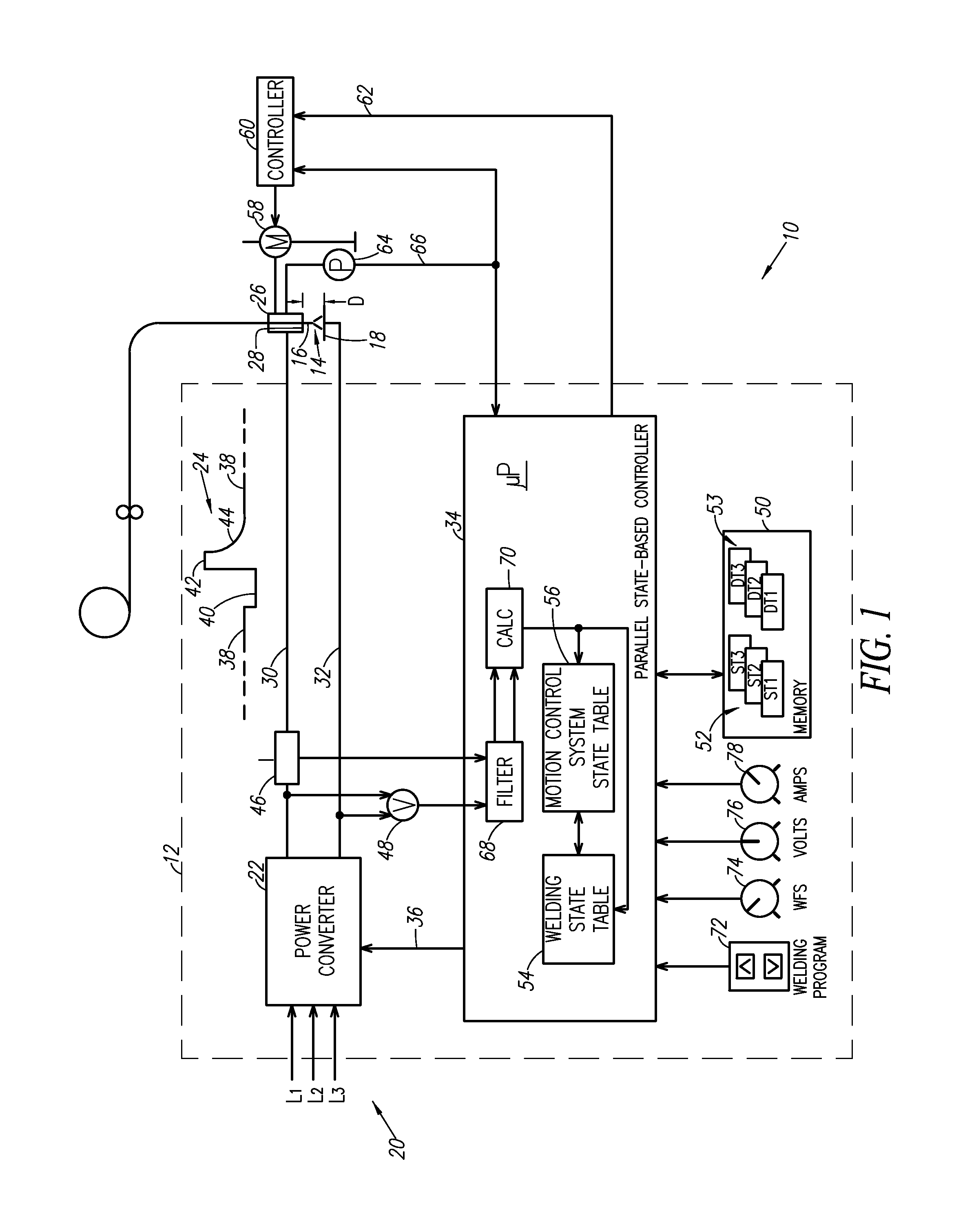
[0046]Turning to FIG. 3, in an example embodiment, the motion control system includes a weaver controller 60a and a weaver motor 58a that can be a part of a through the arc seam tracking system. The weaver motor causes the welding torch 26 to oscillate to perform weave welding movements in accordance with the motion control signal 62. The welding power supply 12 controls both the welding operation and the movements of the welding torch 26 using a parallel state-base...


PUM

PropertyMeasurementUnit
Frequencyaaaaaaaaaa
Lengthaaaaaaaaaa
Sizeaaaaaaaaaa

Abstract

An arc welding system includes a welding torch, an electrode, and a power supply having a switching-type power converter connected to the torch. A parallel state-based controller is connected to the power converter and provides a waveform control signal thereto for controlling its operations. The controller generates a motion control signal for controlling movements of the electrode and/or the torch. A sensor senses welding voltage or welding current. A memory stores a welding state table comprising sequential control states, and stores a motion control system state table comprising further sequential control states. The welding waveform is defined in the welding state table. The controller controls the operations of the power converter through the waveform control signal according to the welding state table, simultaneously adjusting the motion control signal according to the motion control system state table. The controller transitions between control states according to the signal received from the sensor.

Description

BACKGROUND OF THE INVENTION[0001]1. Field of the Invention[0002]The present invention relates to controllers in arc welding systems and to control methodologies for use in arc welding systems.[0003]2. Description of Related Art[0004]State-based control principles can be employed for controlling a welding waveform that is applied to a workpiece during welding. A state table stored in the welding power supply defines the welding waveform through a number of control states respectively corresponding to different parts of the welding waveform. For example, one state could correspond to a peak current of the welding waveform, while another state could correspond to a background current of the welding waveform. Together, the individual states in the state table define the overall welding waveform.[0005]Separate additional controllers (i.e., separate from the welding power supply) are provided for controlling other aspects of the arc welding system. For example, the arc welding system coul...

Claims


Application Information

Patent Timeline
IPC IPC(8): B23K9/10
CPCB23K9/0216B23K9/1006B23K9/122B23K9/173B23K9/073B23K9/08
Inventor PETERS, STEVENHENRY, JUDAHCOLE, STEPHEN
Owner LINCOLN GLOBAL INC
Why Eureka
Try Eureka