
Apparatus, system and method for foreground biased depth map refinement method for dibr view synthesis

a technology of depth map and depth map, applied in the field of image processing, can solve the problems of artifacts or unwanted degredation of images, insufficient information in 2d image alone, and insufficient information in typical depth maps to fill disoccluded regions, so as to avoid incorrect use of foreground texture information and improve the quality of synthesized views

Inactive Publication Date: 2014-01-02
HONG KONG APPLIED SCI & TECH RES INST
View PDF6 Cites 33 Cited by
  • Summary
  • Abstract
  • Description
  • Claims
  • Application Information

AI Technical Summary

Benefits of technology

The present invention provides a method for improving the quality of a synthesized view by avoiding incorrect use of foreground texture information in hole-filling. The method uses the horizontal gradient of the texture edge in a color image to guide the shifting of foreground depth pixels around the large depth discontinuities. This results in a more accurate assignment of foreground depth values to the texture edge pixels, while only using background information for the hole-filling process. Additionally, the depth map quality is not significantly degraded when this method is used for hole-filling.

Problems solved by technology

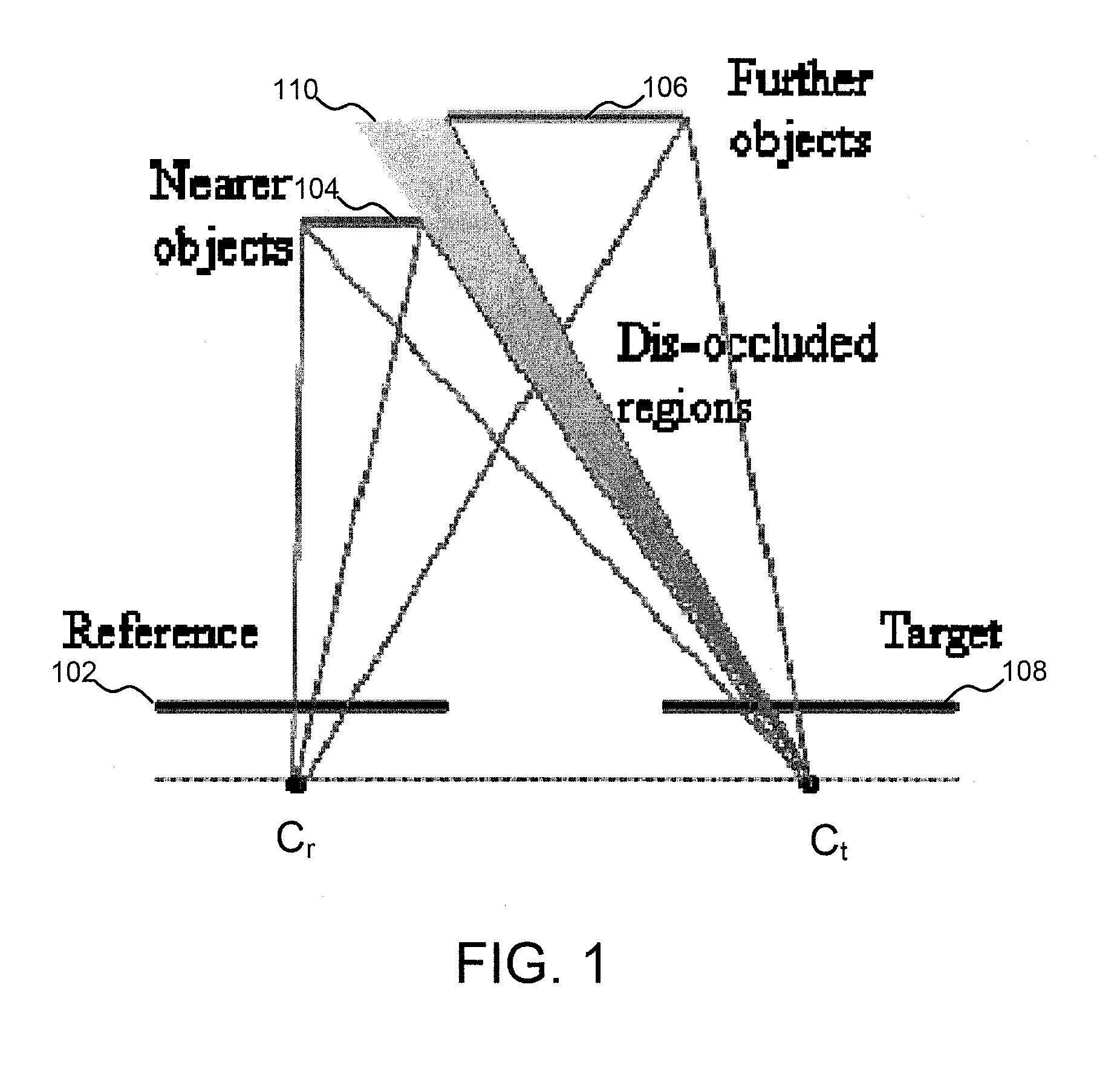
One challenge to synthesize high quality virtual views is to reconstruct the large disoccluded areas after the 3D image warping process.
The 2D image alone may not contain sufficient information to fill in all details for each of the perspectives.
Moreover, typical depth maps may not contain sufficient information to fill disoccluded regions.
Unfortunately, both of these methods generally leave artifacts or unwanted degredation of the image, which can be very annoying to a viewer of the image.
Unfortunately, these hole-filling method also produce annoying artifacts.
Thus, the hole-filling techniques that only consider the planar image information cannot solve the problem.
Artifacts in the synthesized views using depth map information are mainly due to low depth map quality associated with incorrect depth values, especially for texture edge pixels that include foreground and background color pixels.
Consequently, unprocessed depth map usually cause artifacts after the hole filling process.
The artifacts created in such hole-filling processes may be reduced, but the depth map may be highly degraded.
The highly degraded depth map may cause a poverty of 3D perception of the synthesized view.
This method requires more than one view to solve this problem and is not suitable for the view synthesis with single texture video such as video-plus-depth based DIBR applications.

Method used


Image

  • Apparatus, system and method for foreground biased depth map refinement method for dibr view synthesis
  • Apparatus, system and method for foreground biased depth map refinement method for dibr view synthesis
  • Apparatus, system and method for foreground biased depth map refinement method for dibr view synthesis

Examples


Embodiment Construction

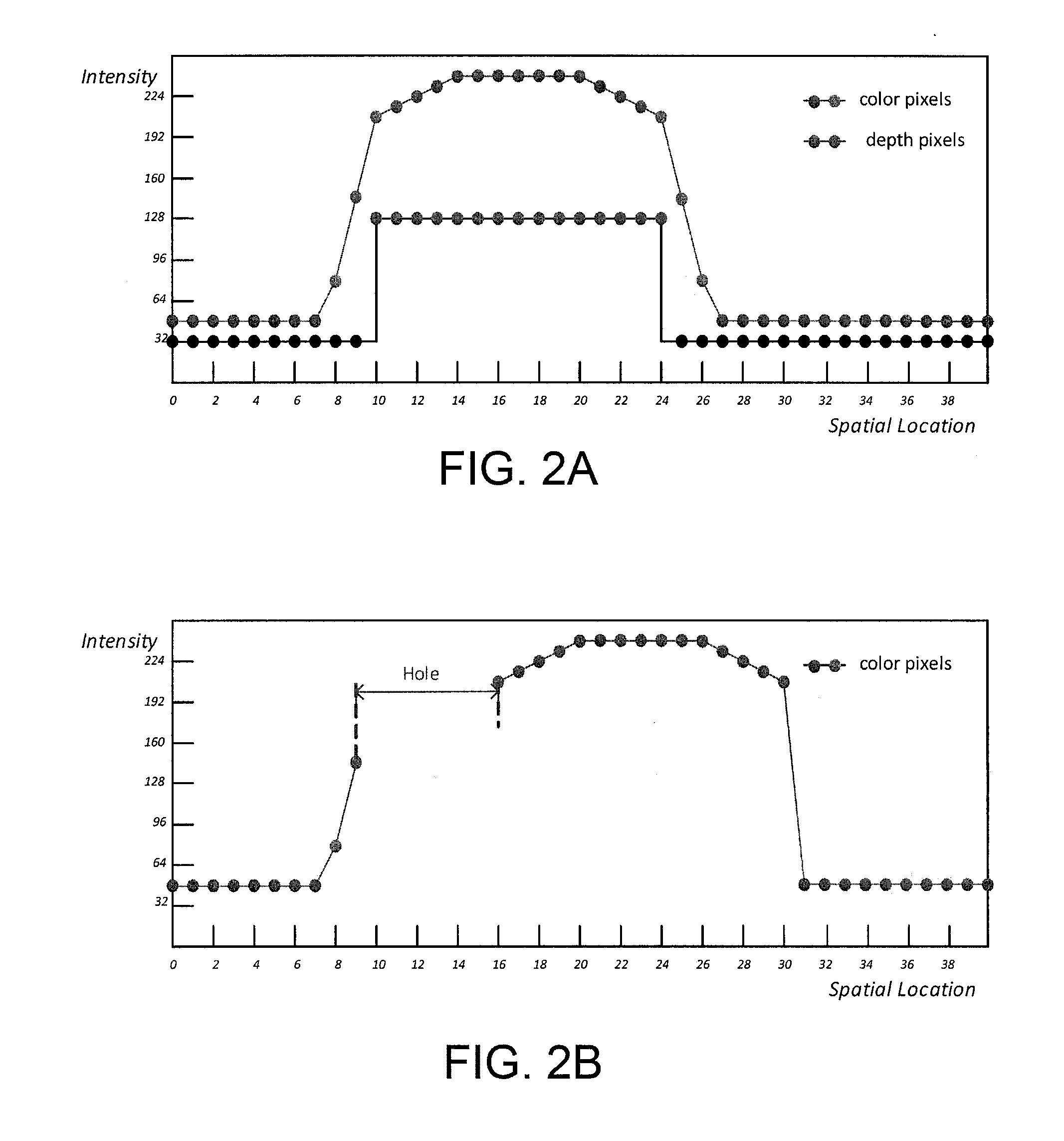
[0031]Characteristics of depth map and natural color image have many differences. Depth map represents distance between an object and a camera as a gray that has large homogeneous regions within scene objects and sudden changes of depth values at object boundaries. Thus, the edges of depth map are typically very sharp. However, most of the edges in color image are changing smoothly over a transition region. To illustrate these differences, FIG. 2A shows color pixel intensive values and depth pixel values of a horizontal line in a color image. There are two smooth edges of an object with sharp depth edges in the corresponding depth map. In the case of FIG. 2A, these two depth object boundaries are aligned at the middle of the transitional color edges. However, depth map that captured by depth camera or estimated from video frames may not aligned correctly. These depth edges may be misaligned at the foreground regions or background regions as shown in FIG. 3A and FIG. 3B, respectively...


PUM


Abstract

The present embodiments include methods, systems, and apparatuses for foreground biased depth map refinement in which horizontal gradient of the texture edge in color image is used to guide the shifting of the foreground depth pixels around the large depth discontinuities in order to make the whole texture edge pixels assigned with foreground depth values. In such an embodiment, only background information may be used in hole-filling process. Such embodiments may significantly improve the quality of the synthesized view by avoiding incorrect use of foreground texture information in hole-filling. Additionally, the depth map quality may not be significantly degraded when such methods are used for hole-filling.

Description

TECHNICAL FIELD[0001]The present invention relates generally to image processing and, more particularly, to apparatuses, systems, and methods for foreground biased depth map refinement method for Depth Image Based Rendering (“DIBR”) View Synthesis.BACKGROUND OF THE INVENTION[0002]Video-plus-depth format is an efficient way to represent 3D video. This format typically includes 2D color texture video and depth map with per pixel depth information. This is a very compact format, which has been especially suitable for mobile 3D video applications. Moreover, video-plus-depth format has high feasibility to render views with variable baseline by DIBR. Thus, stereo video and multiview video can be generated for stereoscopic or auto-stereoscopic 3D display devices using such methods.[0003]Synthesizing new views using DIBR involves three major steps: (1) depth map preprocessing, (2) 3D image warping, and (3) hole filling. One challenge to synthesize high quality virtual views is to reconstruc...

Claims


Application Information

Patent Timeline
Patent Type & Authority Applications(United States)
IPC IPC(8): H04N13/00
CPCH04N2213/003H04N13/111
Inventor PO, LAI MANXU, XUYUANREN, JUNYAN
Owner HONG KONG APPLIED SCI & TECH RES INST
Learn More