Article Storage System and Maintenance Method in Article Storage System

Active Publication Date: 2014-01-02
DAIFUKU CO LTD
View PDF11 Cites 10 Cited by
  • Summary
  • Abstract
  • Description
  • Claims
  • Application Information

AI Technical Summary

Benefits of technology

[0008]More particularly, the traveling body of the stacker crane is separable into the lower traveling portion and the upper traveling portion by separating the post of the stacker crane into the lower post portion and the upper post portion. Since the position where the lower post portion is separated from the upper post portion is at the level lower than the predetermined level at which the attached apparatus is mounted, the level of the lower traveling portion in the separate state separated from the upper traveling portion is lower than the predetermined level at which the attached apparatus is mounted. Therefore, the lower traveling portion in the separated state is movable under the attached apparatus with its traveling posture being maintained, as a result of which the lower traveling portion in the separated state can be taken in or out through the underside of the attached apparatus between the moving space and the take-in/out space adjacent to the one side of the moving space without detaching the attached apparatus.
[0009]Incidentally, possible maintenance work that requires a large space includes replacement of a propelling motor for propelling the traveling carriage or a lifting motor for raising or lowering the lift body. Since those propelling motor and the lifting motor are provided in or in the vicinity of the traveling carriage, the lower traveling portion is conveyed from the moving space to the take-in/out space, and the propelling motor and lifting motor also can be conveyed to the outside of the moving space along with the lower traveling portion. Thus, the replacement of the propelling motor or lifting motor can be done easily. The possible maintenance work that requires a large space also includes replacement of the lift body.

Problems solved by technology

On the other hand, it is difficult for the operator to perform the maintenance work with the stacker crane being positioned in the moving space if some major maintenance work has to be done including exchange of a propelling motor for propelling a traveling carriage, exchange of a lifting motor for raising or lowering a lift deck, or exchange of the lift deck, for example.
Further, it is neces

Method used


Image

  • Article Storage System and Maintenance Method in Article Storage System
  • Article Storage System and Maintenance Method in Article Storage System
  • Article Storage System and Maintenance Method in Article Storage System

Examples


Embodiment Construction

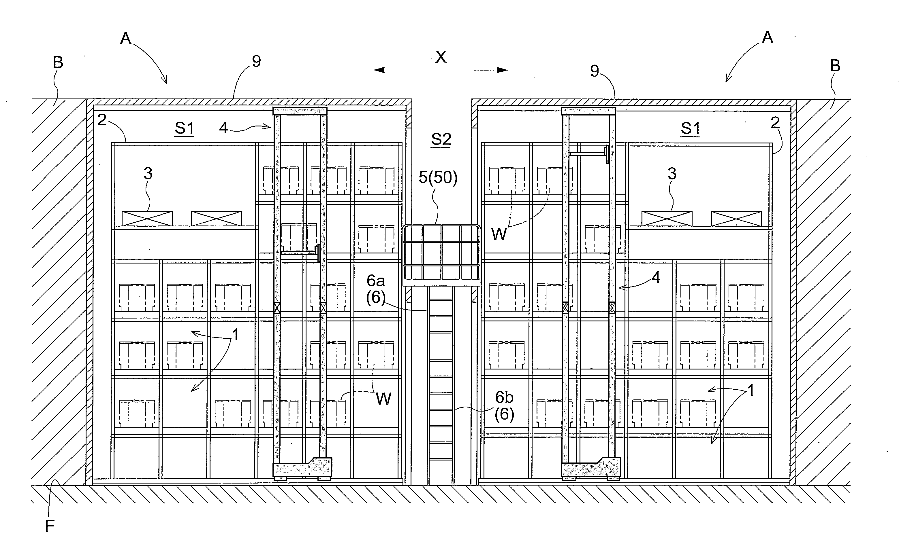
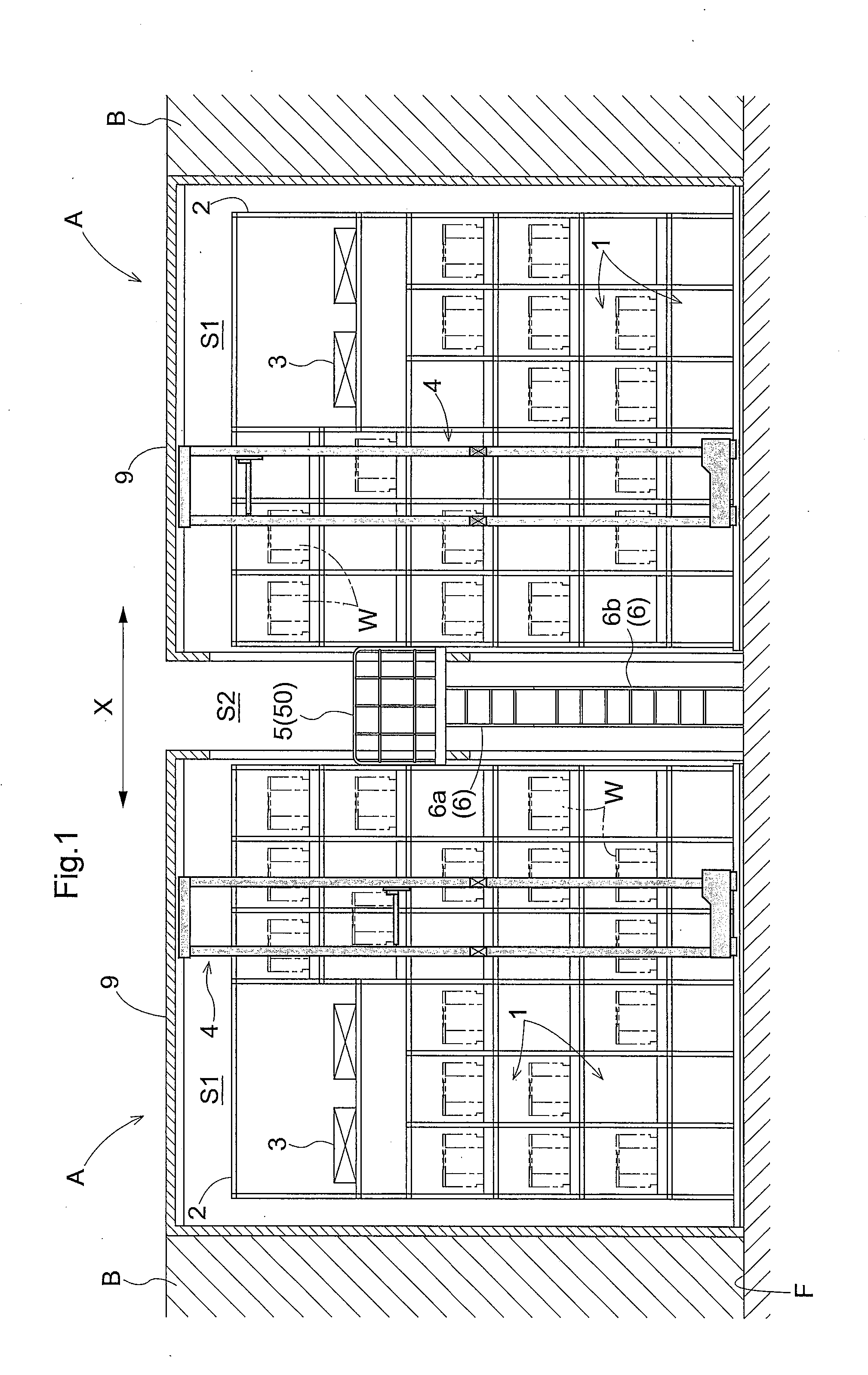
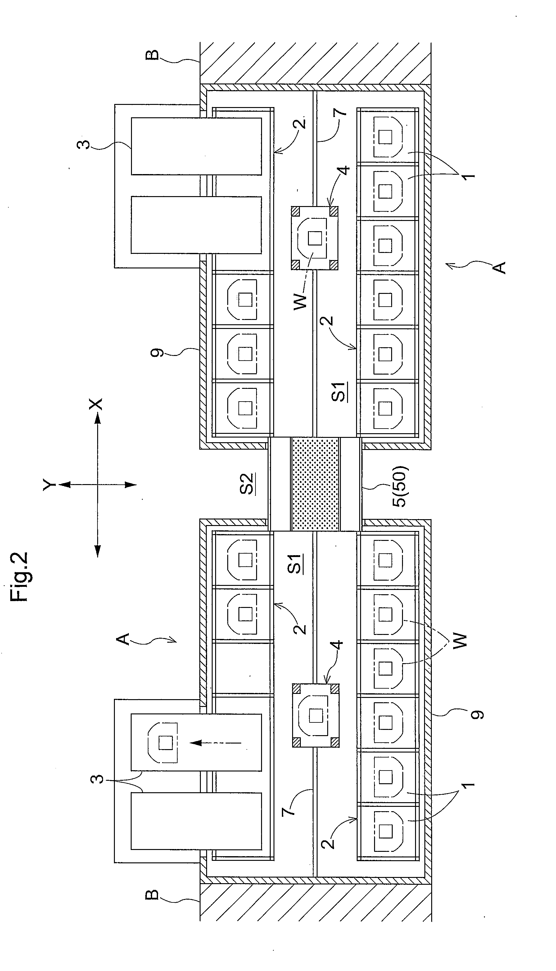
[0018]An embodiment of an article storage system according to the present invention will be described hereinafter in reference to the accompanying drawings. As shown in FIGS. 1 and 2, the article storage system includes a plurality of storage portions 1 arranged in a vertical direction and a width direction in an article storage shelf 2, a transport device 3 for stock and delivery of an article, a stacker crane 4 for transferring the article between the storage portion 1 and the transport device 3, and a platform 5 for the operator to access an upper part (upper space) of a moving space 51 for the stacker crane 4 from one side of the width direction (first end side of a transverse direction). FIG. 1 is a side view of the article storage system in vertical section, in which the width direction of the article storage shelf 2 is shown in arrow X. FIG. 2 is a top plan view of the article storage system, in which the width direction of the article storage shelf 2 is shown in arrow X whil...


PUM

PropertyMeasurementUnit
Widthaaaaaaaaaa

Abstract

A traveling body of a stacker crane is separable into a lower traveling portion and an upper traveling portion by separating a post into a lower post portion and an upper post portion, in which the lower traveling portion in a separated state separated from the upper traveling portion and supporting a lift body is moved in a width direction with its traveling posture being maintained to be taken in or out between a moving space and a take-in/out space.

Description

FIELD OF INVENTION[0001]The present invention relates to an article storage system and a maintenance method in the article storage system.BACKGROUND[0002]An article storage system is known which includes a pair of article storage shelves facing each other and a stacker crane traveling in a moving space formed between the pair of article storage shelves for transporting an article. In such an article storage system, an attached apparatus may be mounted in the vicinity of one side of the moving space in a width direction at a predetermined level lower than the stacker crane. As the attached apparatus, a transport device may be provided for supplying or delivering the article to / from an upper part of the article storage system, or a platform may be provided for the operator to access the upper part of the moving space from one side of the moving space in the width direction (first end side of a transverse direction) for maintenance work, for example.[0003]Japanese Unexamined Patent App...

Claims


Application Information

Patent Timeline
IPC IPC(8): B65G1/04
CPCB65G1/0407B66F9/07Y10T29/49721Y10T29/49819B65G1/04B60S11/00B65G1/0428B65G1/0492B66F9/075B66F9/08
Inventor TAKAHARA, FUMIOKAWAMURA, SHINSUKE
Owner DAIFUKU CO LTD
Why Eureka
Try Eureka