Side dam with insert

Inactive Publication Date: 2014-01-09
NUCOR CORP
View PDF2 Cites 5 Cited by
  • Summary
  • Abstract
  • Description
  • Claims
  • Application Information

AI Technical Summary

Benefits of technology

[0005]The length of a casting campaign of a twin roll caster has been generally determined in the past by the useful life of the core nozzle, tundish and side dams. Multi-ladle sequences can be continued by use of a turret allowing sequential ladles of molten metal to be transferred to the operating position. The focus in extending casting campaigns, therefore, has been extending the useful life of the core nozzle, tundish and side dams, and in turn reducing the cost per ton of casting thin strip. Wear and replacement of the side dams has usually limited the casting campaign, where the casting campaign was typically stopped and the worn side dams replaced. The core nozzles and tundish with remaining useful life were typically replaced at the same time so the length of the next campaign is not limited, with attendant waste of useful life of refractories and increased cost of casting steel. In the past, one focus has been on improving refractory materials. Graphitized alumina, boron nitride and boron nitride-zirconia composites are examples of suitable refractory materials for the side dams, tundish and core nozzle components. SiAlON (i.e, silicon alumina oxy-nitride) refractory material has also been proposed for use in making side dams.
[0006]Also, the side dams wear independently of the core nozzles and tundish, and independently of each other. The side dams must initially be urged against the ends of the casting rolls under biasing forces, and “worn-in” to be adequately seated against outflow of molten steel from the casting pool. The biasing forces applied to the side dams may be reduced after an initial wear-in period, but there continued to be significant wear of the

Problems solved by technology

As the casting rolls are rotated, the side dams experience frictional wear, causing arc-shaped grooves to form in the side dams along the circumferential surfaces of the casting rolls.
Wear and replacement of the side dams has usually limited the casting campaign, where the casting campaign was typically stopped and the worn side dams replaced.
The core nozzles and tundish with remaining useful life were typically replaced at the same time so the length of the next campaign is not limited, with attendant waste of useful life of refractories and increased cost of casting steel.
Also, the side dams wear independe

Method used


Image

  • Side dam with insert
  • Side dam with insert
  • Side dam with insert

Examples


Example

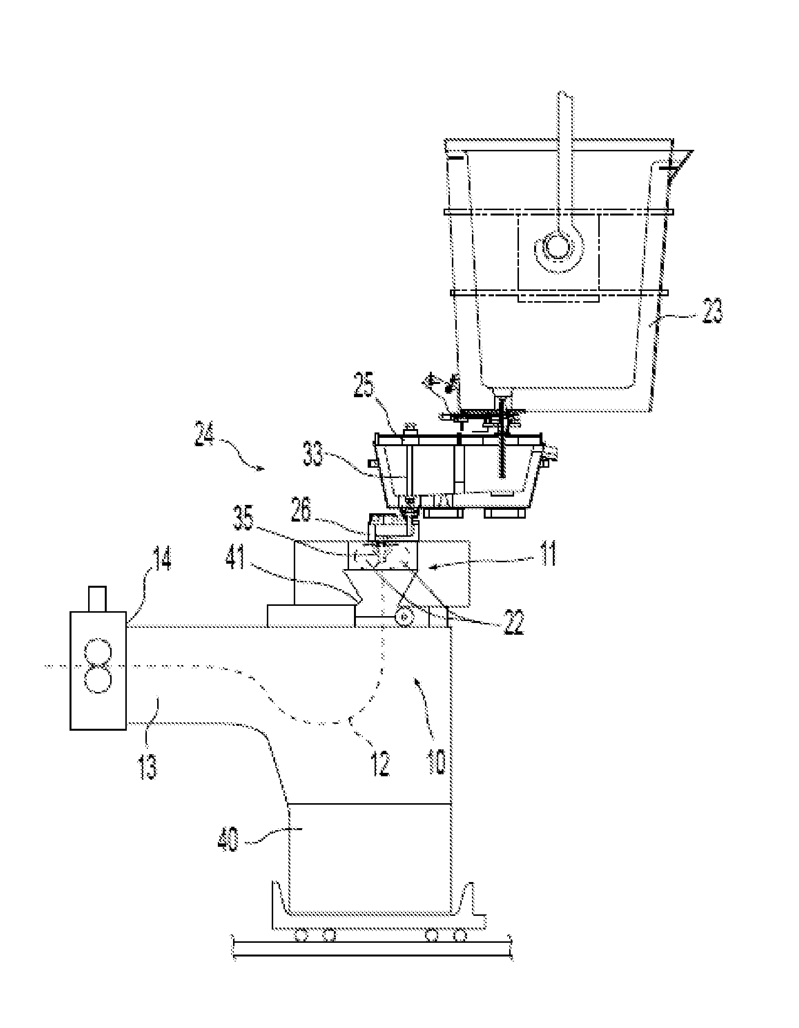
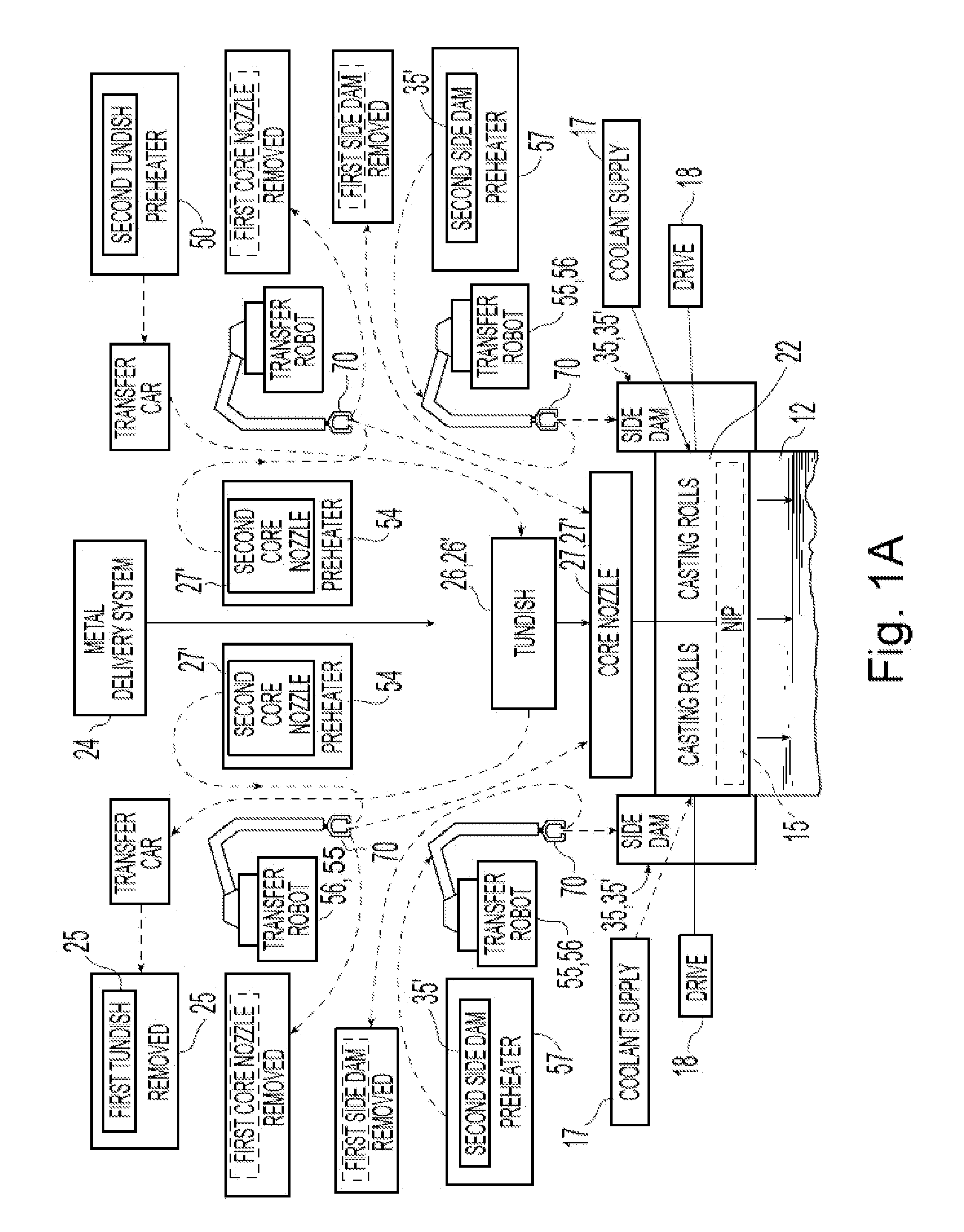
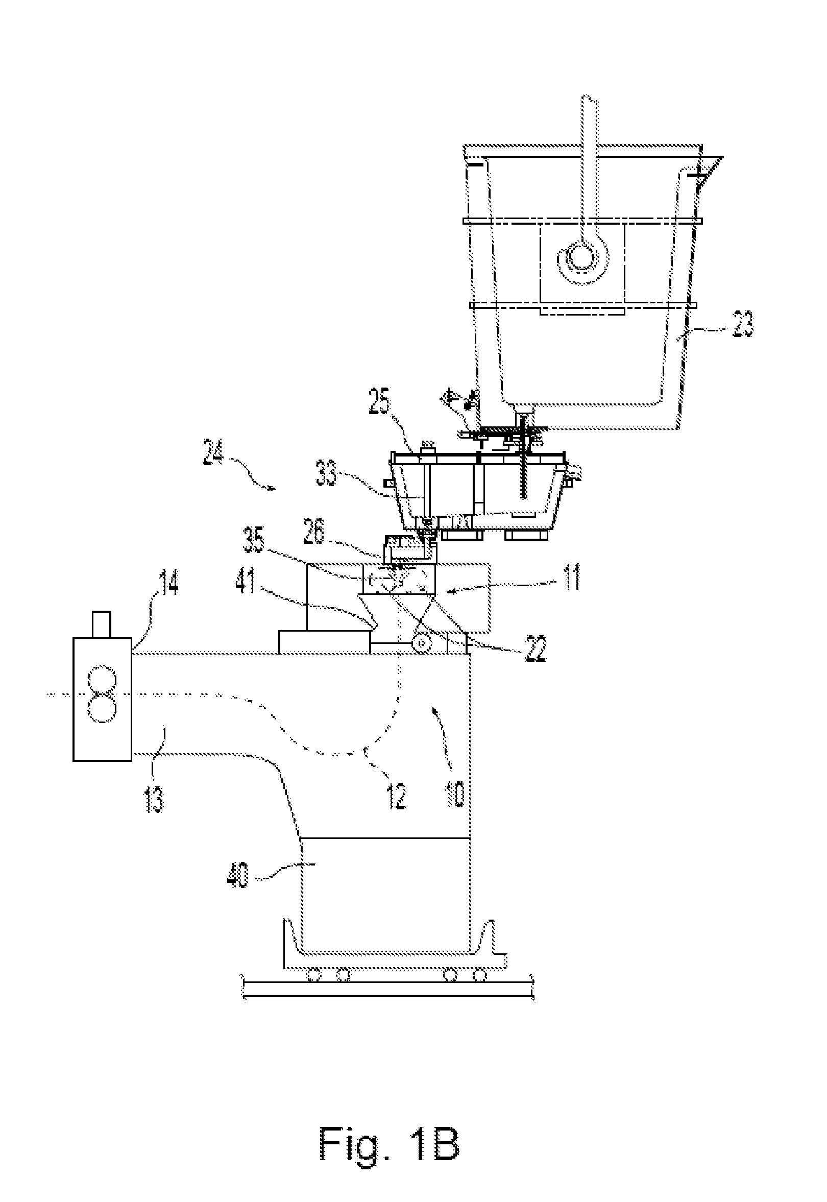
[0026]FIGS. 1A-1G illustrate various aspects of an exemplary continuous twin roll caster system. The illustrative twin roll caster comprises a twin roll caster denoted generally as 11 producing a cast steel strip 12 which passes within a sealed enclosure 10 to a guide table, which guides the strip to a pinch roll stand 14 through which it exits the sealed enclosure 10. The seal of the enclosure 10 may not be complete, but appropriate to allow control of the atmosphere within the enclosure and limit access of oxygen to the cast strip within the enclosure as hereinafter described. After exiting the sealed enclosure 10, the strip may pass through other sealed enclosures and may be subjected to in-line hot rolling and cooling treatment.

[0027]Twin roll caster 11 comprises a pair of laterally positioned casting rolls 22 forming a nip 15 there between, to which molten metal from a ladle 23 is delivered through a metal delivery system 24. Metal delivery system 24 comprises a tundish 25, a r...


PUM

PropertyMeasurementUnit
Lengthaaaaaaaaaa
Lengthaaaaaaaaaa
Fractionaaaaaaaaaa

Abstract

A composite side dam for a continuous twin roll caster includes a substrate made of a refractory material capable of withstanding casting temperature and having edge portions adapted to engage casting rolls and having a nip portion adjacent a nip between casting rolls and upper portions extending across the side dam to form a lateral restraint for a casting pool, an insert of at least 10 mm in thickness positioned in a pocket in the substrate and extending to engage the molten metal and extending from the upper portions of the substrate and positioned in the pocket to within 30 mm from the nip portion by insertion adjacent the upper portions of the substrate, and the insert adapted to fit into the pocket of the substrate to form a side dam formed of a refractory material having consumption rate less than 10 mm per hour. The material forming the insert may be between 40 and 60% SiAlON material and the remainder hBN material, or mullite material as described by FIG. 11, or between about 60 and 63 mole percent Al2O3 and the remainder SiO2, or fused silica, such as between 40 and 60% fused SiO2 and the remainder hBN material.

Description

BACKGROUND AND SUMMARY[0001]This invention relates to the casting of metal strip by continuous casting in a twin roll caster.[0002]In a twin roll caster, molten metal is introduced between a pair of counter-rotated casting rolls that are cooled so that metal shells solidify on the moving roll surfaces and are brought together at a nip between them. The term “nip” is used herein to refer to the general region at which the rolls are closest together. The molten metal may be delivered from a ladle into a smaller vessel or series of smaller vessels from which it flows through a metal delivery nozzle located above the nip, forming a casting pool of molten metal supported on the casting surfaces of the rolls immediately above the nip and extending along the length of the nip. As the molten metal formed into shells are joined and pass through the nip between the casting rolls, a thin metal strip is cast downwardly from the nip.[0003]The casting pool is usually confined between side dams he...

Claims


Application Information

Patent Timeline
IPC IPC(8): B22D11/06
CPCB22D11/066B22D11/0622
Inventor ONDROVIC, JAY JONDENO, ALAN J.SCHLICHTING, MARKMAHAPATRA, RAMA BALLAV
Owner NUCOR CORP
Why Eureka
Try Eureka