Image display device

a display device and image technology, applied in the field of image display devices, can solve the problems of increasing crosstalk, unfavorable mobile applications such as tablets, increasing crosstalk, etc., and achieve the effects of suppressing the average aperture ratio, reducing the viewing distance, and reducing the moiré

Inactive Publication Date: 2014-01-09
PANASONIC INTELLECTUAL PROPERTY CORP OF AMERICA
View PDF105 Cites 14 Cited by
  • Summary
  • Abstract
  • Description
  • Claims
  • Application Information

AI Technical Summary

Benefits of technology

[0011]According to the aforementioned image display device, by alternately arranging parallax images in sub-pixel units per two image rows, a proper viewing distance may be shortened and moiré may be reduced by widening an aperture up to a width corresponding to two

Problems solved by technology

However, with regard to the first prior art example, in which parallax images are alternately arranged in sub-pixels per an image row, it has been pointed out that there is a problem of a longer distance (a proper distance) from a display screen to an observer to allow preferable observation for the observer if a sub-pixel size is small and if a distance is consistent from a display panel and an image separating means.
I

Method used


Image

  • Image display device
  • Image display device
  • Image display device

Examples


first embodiment

[0067]As the first embodiment of the present invention, a device which alternately arranges parallax images in sub-pixel units per two image rows and has a slant barrier aperture with an inclination of 3:2 is described with reference to FIGS. 1 to 9.

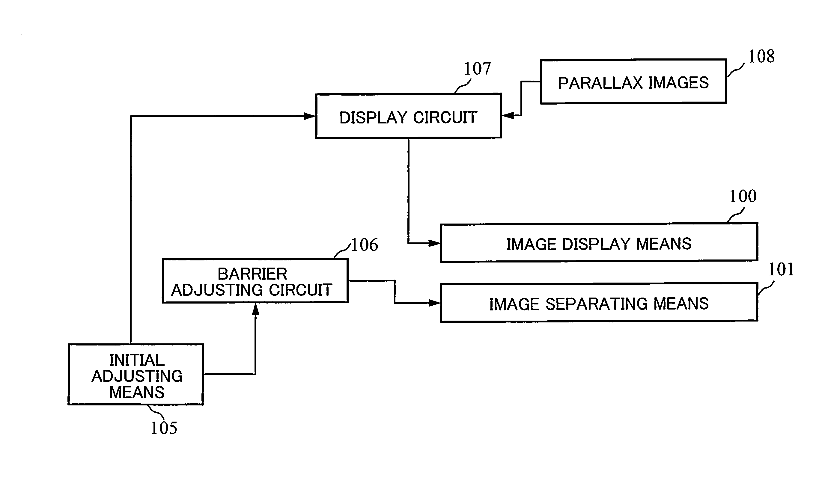
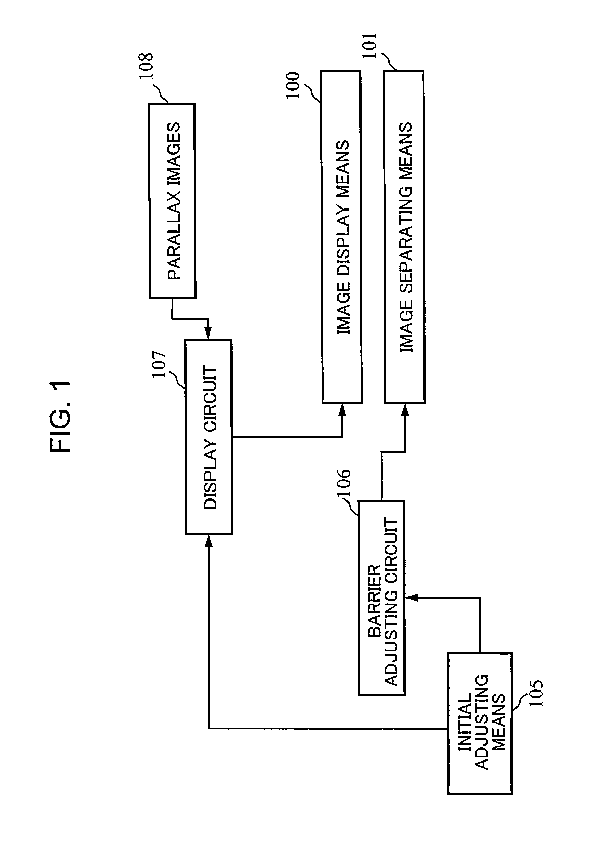
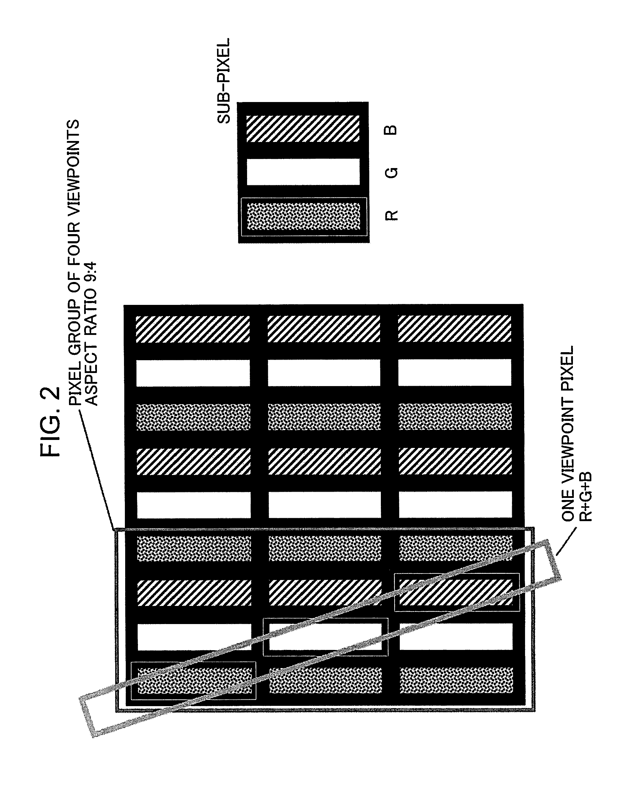
[0068]FIG. 1 shows a configuration of an image display device as the first embodiment of the present invention. FIG. 2 shows an image arrangement in which parallax images are alternately arranged per an image row and a slant barrier example 1 with an inclination of 3:1, which are used in conventional examples. FIG. 3 shows an image arrangement example 1, in which parallax images are alternately arranged in sub-pixel units per two image rows, and the slant barrier example 1 with an inclination of 3:2. FIG. 4 schematically shows how an adjacent pixel becomes observed through a slant barrier aperture when the head is moved in the first embodiment. FIGS. 2 to 4 show exemplary cases where parallax number n=4. In FIGS. 2 to 4, a screen on whic...

second embodiment

[0082]The second embodiment of the present invention is described with reference to FIGS. 1 and 10 to 17. As the second embodiment, a pixel arrangement example 2, in which parallax images are alternately arranged in sub-pixel units per two image rows, and stereoscopic image display by means of a slant barrier aperture 4 with an inclination of 3:1 are described.

[0083]The present invention is configured as shown in FIG. 1. The operations are similar to those of the first embodiment. FIG. 10 schematically shows the pixel arrangement example 2 in the second embodiment, in which parallax images are alternately arranged in sub-pixel units per two image rows, and a slant barrier aperture 4 with an inclination of 3:1. FIG. 11 is a schematic view showing how an adjacent pixel becomes observed through the slant barrier aperture 4 when the head is moved with respect to the image display device. An inclination angle of the slant barrier with respect to the vertical direction is 18.435 degrees (...

modification example 1

[0084]As a modification example 1, the example 5 is described with reference to FIG. 12 in which a barrier pattern is provided with a fine notched structure so that an aperture width periodically varies so as to be horizontally symmetrical and irregularities are added to an aperture edge so that an amount / range of blur of pixels observed through a barrier may be controlled. Like the modification example 2 of the first embodiment, the modification example 1 of the second embodiment facilitates moiré reduction by adding the uneven structure (notched structure) described with reference to FIGS. 8 and 9 to an aperture edge. By adopting this method, a reduction in crosstalk may be simultaneously achieved since moiré may be reduced with setting the average aperture ratio Ave_rh to a smaller value (e.g. sp×1.2 to sp×1.6) than sub-pixel sp×2. With keeping the pixel-size average aperture ratio Ave_rh at ThAve_rH, further crosstalk reduction may be achieved by suppressing the maximum aperture...


PUM


Abstract

A parallax composite image displayed by image display means is separated by image separating means so that parallax images are observed at a predetermined position. Parallax images are alternately arranged for each of image rows in the parallax composite image. If the separating means has an inclination angle between 10 and 15 degrees and if a center of the separating means and a center of a pixel exist at a predetermined interval, crosstalk may be suppressed and a proper viewing distance may be shortened. By providing the image separating means with a notched structure of which aperture width periodically varies, adding irregularities to an aperture edge, and controlling an amount of blur of pixels observed through the aperture or alike, moiré reduction may be achieved.

Description

CROSS-REFERENCE TO RELATED APPLICATIONS[0001]This application is based on Japanese Patent Application No. 2012-154075 filed on Jul. 9, 2012, the contents of which are hereby incorporated by reference.BACKGROUND OF THE INVENTION[0002]1. Field of the Invention[0003]The present invention relates to an image display apparatus configured to allow a stereoscopic image observed without special eyeglasses.[0004]2. Description of the Related Art[0005]With regard to devices for displaying stereoscopic images without special eyeglasses, a device is known as a prior art in which a parallax barrier, a lenticular lens or alike (spectroscopic means) is arranged on the observer side of a display device such as a liquid crystal panel or a plasma display panel (PDP) to separate light from left-eye and right-eye images displayed on a display panel to the left and right in order to display a stereoscopic image.[0006]FIG. 30 shows principles of an eyeglass-free stereoscopic image display device which us...

Claims


Application Information

Patent Timeline
IPC IPC(8): G09G5/14G02B30/31G02B30/32
CPCG09G5/14G09G3/003G09G2300/0439G09G2320/0209H04N13/315H04N13/317H04N13/398G02B30/31G02B30/32G02B30/27
Inventor WATANABE, TATSUMIMASHITANI, KENKUNIEDA, NOBUYUKI
Owner PANASONIC INTELLECTUAL PROPERTY CORP OF AMERICA
Why Eureka
Try Eureka