Method and Apparatus for Enhanced Routing within a Shortest Path Based Routed Network Containing Local and Long Distance Links

a technology of local and long distance links and enhanced routing, applied in the field of network routing, can solve the problems of affecting the size to which the network can grow, increasing congestion and traffic back-pressure in the fabric, and high cost of the technology and infrastructure needed

Active Publication Date: 2014-01-09
AVAGO TECH INT SALES PTE LTD
View PDF10 Cites 27 Cited by
  • Summary
  • Abstract
  • Description
  • Claims
  • Application Information

AI Technical Summary

Benefits of technology

[0023]Embodiments according to the present invention utilize a Location ID in addition to normal information to allow development of non-shortest path routes. The edge switches which terminate the distance links between locations are identified. Shortest path routes are determined and used for all switches in the same location. For each switch, routes over the distance links to other locations are determined, noting or marking the interface connected to the distance links for edge switches and coupled to an edge switch with a distance link for non-edge switches. The two determined sets of routes are combined with a few limitations. For devices directly connected to the switch, use all eligible interfaces to reach the other location. For all Inter-Switch Links (ISLs), use only routes between a marked and non-marked interface and vice versa. Remove all ISL routes between two marked or two non-marked interfaces. This operation for the directly connected switches results in the possibility of single hops that are non-shortest path to an edge switch and removes certain potential loopback situations due to shortest path routes. With this operation better use is made of parallel distance links that when occur is only shortest path routing was used.

Problems solved by technology

To provide connectivity between the locations, much of the technology and infrastructure needed can be very costly and relatively low throughput.
As demands for data and processing grow larger, these inter-location links continue to be a source of the most significant bottlenecks when routing traffic between locations.
The discrepancies between the relatively low throughput inter-location links and the high throughput intra-location links adds to the congestion and traffic back-pressure experienced throughout the fabric.
But, it also means that all network elements must know about all available paths within the network and this starts impacting the size to which the network can grow.

Method used


Image

  • Method and Apparatus for Enhanced Routing within a Shortest Path Based Routed Network Containing Local and Long Distance Links
  • Method and Apparatus for Enhanced Routing within a Shortest Path Based Routed Network Containing Local and Long Distance Links
  • Method and Apparatus for Enhanced Routing within a Shortest Path Based Routed Network Containing Local and Long Distance Links

Examples


Embodiment Construction

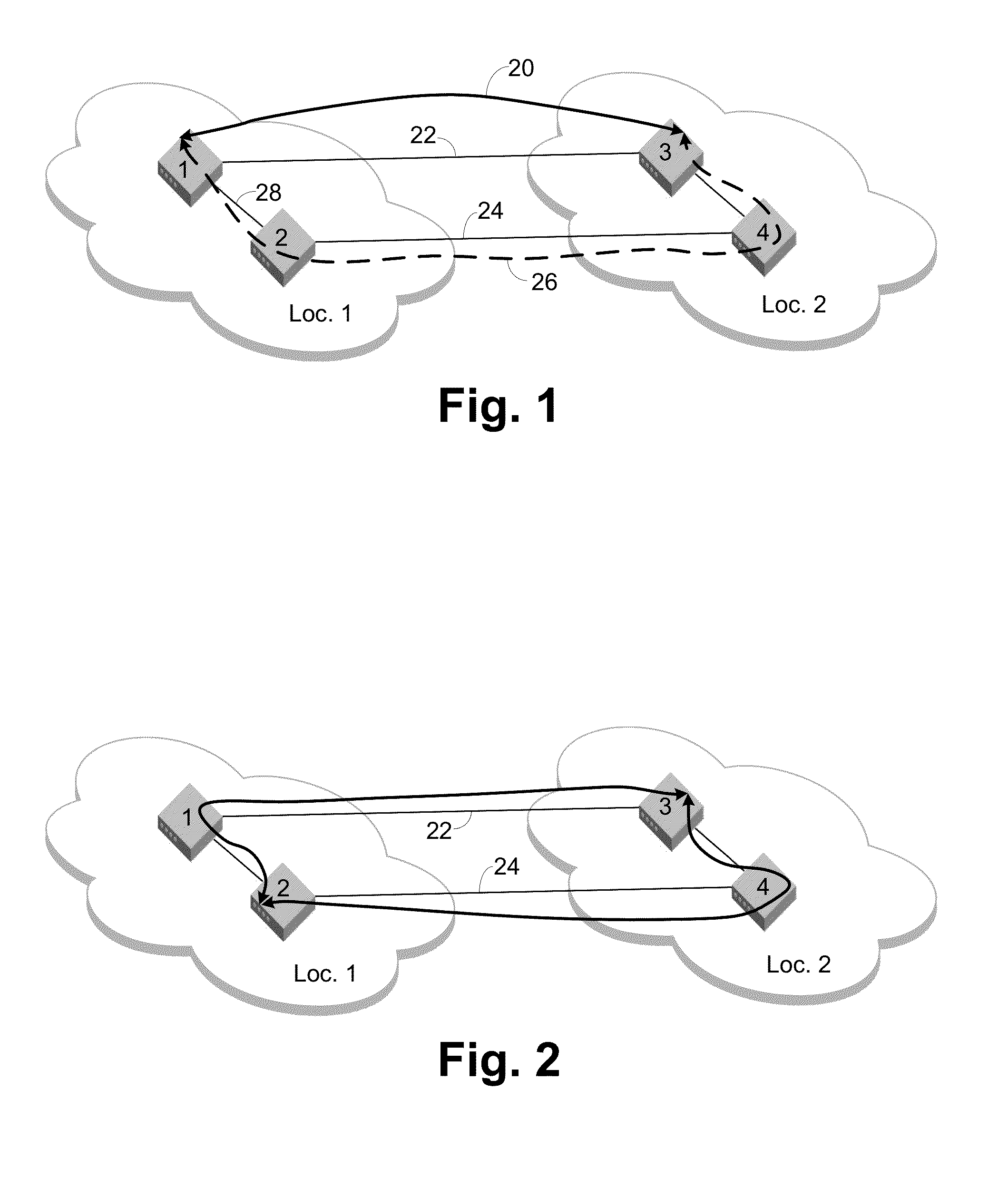
[0033]FIG. 1 shows a simple example network that demonstrates the principles of non-shortest path routing. Assume there are one or more devices attached to switch 1 in location 1 and they are communicating with one or more devices attached to switch 3 in location 2. Following shortest path routing rules, the path 20 between these devices uses the directly connected link 22 as represented by the solid black line. If the required throughput of these devices is greater than the available bandwidth of the link 22, then the link 22 is the bottleneck point. The devices can only pass as much traffic as the link 22 can handle. If the inter-location hops are long distance links, they are likely to be the greatest source of delay for a frame traversing between the locations. Due to the shortest path routing rules, these devices would be unable to use bottom link 24 between switches 2 and 4.

[0034]Since long distance hops typically have a high latency in comparison to the short hops within a lo...


PUM


Abstract

Use of a Location ID in addition to normal information to allow development of non-shortest path routes. The edge switches which terminate the distance links between locations are identified. Shortest path routes are determined for all switches in the same location. For each edge switch, routes over the distance links to other locations are determined, marking the interface connected to the distance links. The two determined sets of routes are combined. For devices directly connected to the edge switch, only the marked interface is used to reach the other location. For switches directly connected to the edge switch, use only routes from non-marked interfaces to marked interfaces and remove any routes from marked to marked or non-marked to non-marked interfaces. This operation for the directly connected switches allows single hops that are non-shortest path to an edge switch and removes certain potential loopback situations due to shortest path routes.

Description

CROSS REFERENCE TO RELATED APPLICATIONS[0001]This application claims the benefit under 35 U.S.C. §119(e) of U.S. Provisional Patent Application Ser. No. 61 / 664,552 entitled “Localization of FSPF,” filed Jun. 26, 2012, which is hereby incorporated by reference.BACKGROUND OF THE INVENTION[0002]1. Field of the Invention[0003]The invention relates to network routing and more particularly routing between separated fabrics.[0004]2. Description of the Related Art[0005]The increasing demands for network and fabric redundancy and resiliency have driven many users to adopt geographically separated locations for replication of data and processing. These locations may be as close as neighboring buildings or as far as separate countries. Frequently, these networks stretch across many states or even a country. Despite the great distances, the locations continue to act as a single network.[0006]To provide connectivity between the locations, much of the technology and infrastructure needed can be v...

Claims


Application Information

Patent Timeline
Patent Type & Authority Applications(United States)
IPC IPC(8): H04L12/801H04L12/721H04L45/74
CPCH04L47/12H04L45/12H04L47/125H04L45/54
Inventor BUSCH, SCOTTCARDWELL, ETHANCIESLAR, PETERJOHNSON, HOWARDWILLEKE, JESSE
Owner AVAGO TECH INT SALES PTE LTD
Why Eureka
Try Eureka