Hydro pneumatic lifting system and method

a technology applied in the field of hydraulic pump and lifting system, can solve the problems of waste of energy spent on lifting these parts, and achieve the effects of superior lifting system, superior motion control, adaptability and compliance properties, and excellent motion control

Inactive Publication Date: 2014-01-16
MAIL JACOB
View PDF24 Cites 28 Cited by
  • Summary
  • Abstract
  • Description
  • Claims
  • Application Information

AI Technical Summary

Benefits of technology

[0043]It is the objective of the disclosed invention to provide new means to enhance vertical lifting capability of cargo loads.
[0046]Another specific objective is to provide a superior lifting system, featuring excellent motion control, adaptability and compliance properties.
[0047]Another specific objective is to provide a superior lifting system, featuring improved reliability and durability characteristics.
[0048]Another specific objective is to provide a low maintenance lifting system, featuring improved maintainability characteristics.
[0052]Counterweighted (also known as “counterbalanced”) lifting systems have been applied widely for decades. The novelty of the present invention introduces an exceptional compact mechanism, comprising a fewer number of components, a considerable lighter counterweight mechanism, superior performance attributes and significant energy saving advantages. A most important novelty of the disclosed invention relates to enhanced reliability and durability properties compared to prior art and other existing technologies.

Problems solved by technology

The energy spent to lift these parts is wasted since this energy does not produce any useful work.

Method used


Image

  • Hydro pneumatic lifting system and method
  • Hydro pneumatic lifting system and method
  • Hydro pneumatic lifting system and method

Examples


Embodiment Construction

[0061]Although specific embodiments of the presented invention are described herein with reference to the drawings, it should be understood that such embodiments are by way of example only. They merely illustrate but a small number of the many specific embodiments, which can represent applications of the principles of the present invention. Various changes and modifications, obvious to those skilled in the art to which the present invention pertains, are deemed to be within the spirit, scope and contemplation of the present invention, as further defined in the appended claims.

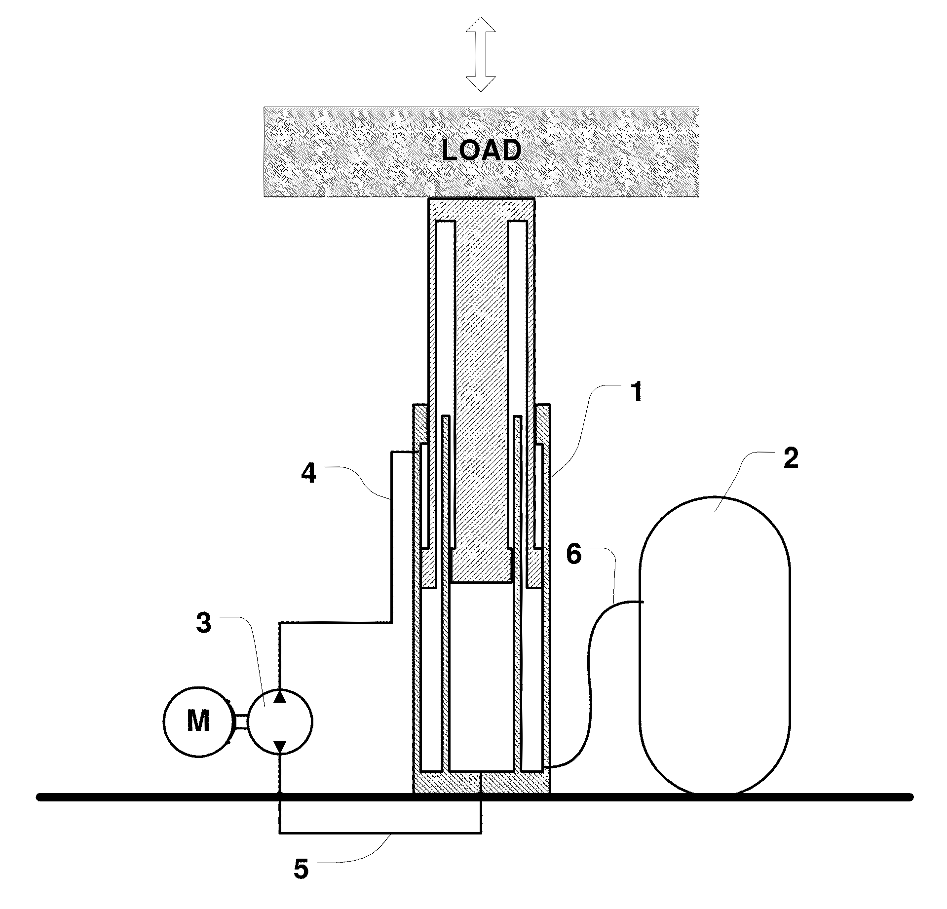
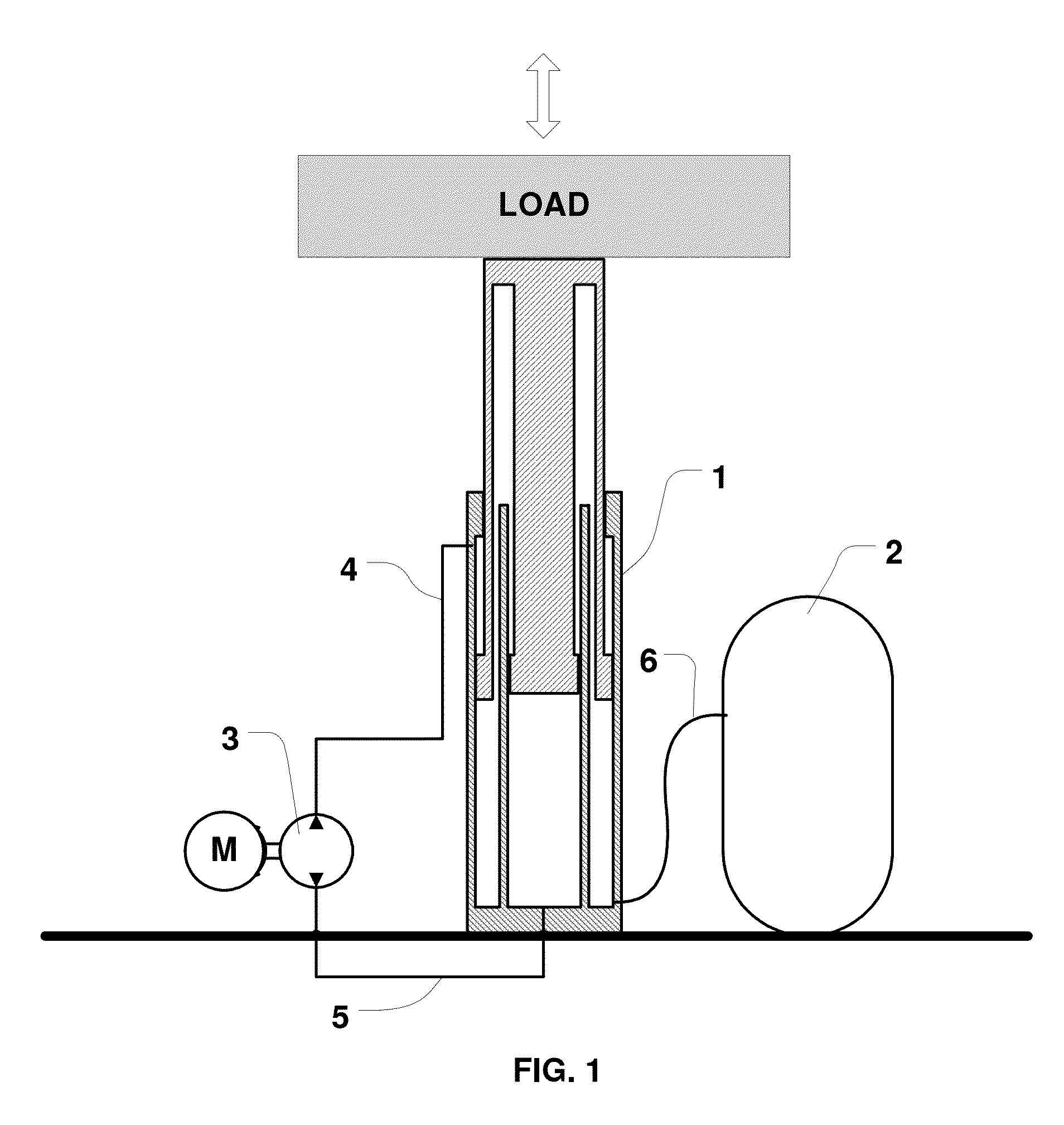
[0062]The disclosed invention introduces a compact, lightweight, hydro-pneumatic system for lifting cargo loads. Typical applications of the disclosed invention include, but are not limited to, man and cargo lifts, cranes, amusement park rides and rod-lifting pumps for extraction of fluids from subsurface formations.

[0063]The use of the disclosed invention for oil extraction from subsurface formations is of spe...


PUM


Abstract

The disclosed invention introduces an efficient lifting mechanism for reciprocating vertically a load system, the load consisting of the aggregate weights of a cargo payload in conjunction with “dead weights” of moving parts of the lifting apparatus.The disclosed invention uses a hydro-pneumatic linear actuator to lift the load and a pressurized accumulator, acting as a force intensifier. The pressurized accumulator, acting as a self-contained stored energy source, provides to the actuator adequate power to lift the “dead weights” plus part of the cargo payload. An external power source provides to the actuator adequate power to lift the remainder of the cargo payload. The disclosed invention saves significant amounts of power and energy in applications in which the “dead weights” are sizable compared to the cargo load. The disclosed invention provides also exceptional means for accurate motion control of the cargo payload.

Description

BACKGROUND OF THE INVENTION[0001]1. Field of the Invention[0002]The disclosed invention relates to the field of lifting mechanisms employed to lift loads vertically. More specifically, it relates to lifting systems wherein the total lifted load comprises relative heavy components of the lifting apparatus itself. Typical embodiments of the disclosed invention apply, but are not limited, to hydraulic lifts, hydraulic cranes and rod lifting hydraulic pumps used to extract fluids from deep subsurface formations.[0003]A typical example of an embodiment of the invention is an elevator lift. The total load lifted by typical elevator lifts includes weights of the cargo car and the cables, in addition to the useful lifted payload of passengers or other cargo. Most frequently, the weights of the cargo car and the cables constitute a significant portion of the total weight. The energy spent on lifting these “dead weights” is pure waste since it is producing useless work.[0004]Another example p...

Claims


Application Information

Patent Timeline
Patent Type & Authority Applications(United States)
IPC IPC(8): E21B19/06B66F3/24
CPCB66B9/04B66F3/26Y02B50/00
Inventor MAIL, JACOB
Owner MAIL JACOB
Why Eureka
Try Eureka