Communication device, communication system and communication method

a communication system and communication device technology, applied in the field of communication devices, communication systems and communication methods, can solve the problems of insufficient improvement in long recovery time, and insufficient improvement of shortening so as to shorten the time when communication is interrupted and prevent communication. , the effect of long recovery tim

Inactive Publication Date: 2014-01-16
BUFFALO CORP LTD
View PDF6 Cites 0 Cited by
  • Summary
  • Abstract
  • Description
  • Claims
  • Application Information

AI Technical Summary

Benefits of technology

[0003]The former proposed technique, however, has the problem of a relatively long recovery time (time when wireless communication is interrupted) to resume wireless communication by another system when wireless communication is interrupted. The latter technique of selecting the communication system based on the signal intensity shortens the time when communication is interrupted by the time interval between reduction of the signal intensity and actual communications blackout and ideally prevents communications blackout. The shorter time interval, however, leads to reduction of the effect of shortening the time when communication is interrupted. This accordingly results in insufficient improvement in shortening the time when communication is interrupted. Especially communication using radio wave in a high frequency band for the purpose of high-speed wireless communication tends to have the shorter time interval and is thus significantly affected by this problem.

Problems solved by technology

The former proposed technique, however, has the problem of a relatively long recovery time (time when wireless communication is interrupted) to resume wireless communication by another system when wireless communication is interrupted.
This accordingly results in insufficient improvement in shortening the time when communication is interrupted.
Especially communication using radio wave in a high frequency band for the purpose of high-speed wireless communication tends to have the shorter time interval and is thus significantly affected by this problem.

Method used


Image

  • Communication device, communication system and communication method
  • Communication device, communication system and communication method
  • Communication device, communication system and communication method

Examples


embodiment 1

Communication System CS (FIG. 1);

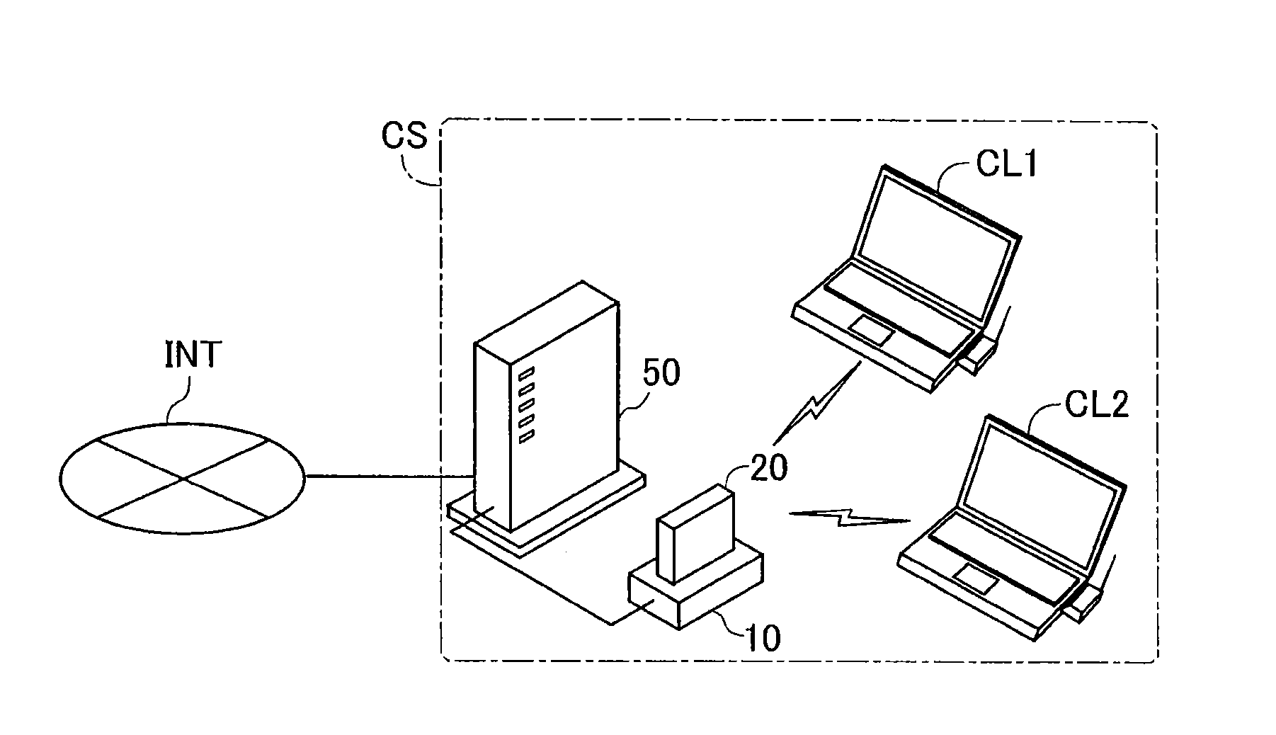
[0015]FIG. 1 illustrates the schematic configuration of a communication system CS. As illustrated in FIG. 1, the communication system CS includes a cradle 10, an access point 20 for wireless LAN and a home gateway 50. The communication system CS connects client devices to a WAN, i.e., the Internet INT according to this embodiment. The cradle 10 has wireless power supply function to wirelessly supply electric power to the access point 20. The home gateway 50 relays communication between the client devices and the Internet INT. According to this embodiment, the client devices are known computers having the functions of wireless LAN client devices. In the illustrated example of FIG. 1, personal computers are client devices CL1 and CL2. The client devices may also include, for example, game machines, smartphones, PDAs and other access points.

[0016]The home gateway 50 serves as a broadband router. The cradle 10 is connected with the home gateway 50 by wir...

embodiment 2

[0051]The description of Embodiment 2 only regards the differences from Embodiment 1. FIG. 8 is a block diagram illustrating the configuration of an access point 20a according to Embodiment 2. The access point 20a is used in place of the access point 20 of Embodiment 1.

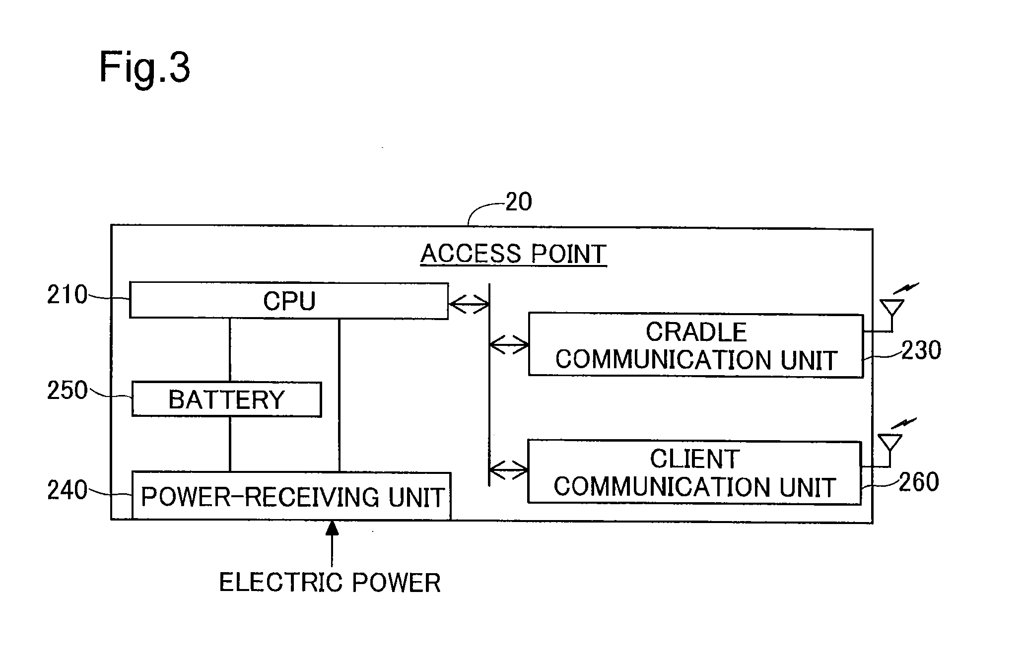
[0052]The primary difference of the access point 20a from the access point 20 is that the access point 20a mainly performs the communication system selection process instead of the cradle 10. The access point 20a has a CPU 210a, in place of the CPU 210, to perform the communication system selection process. The CPU 210a performs the communication system selection process of Embodiment 2 to serve as a first system communication module 212, a communication module 214, a first system communication preparatory module 216 and a communication preparatory module 218. A power-receiving unit 240 of Embodiment 2 is one example of an electric charger.

[0053]The communication system selection process of Embodiment 2 is substantial...

embodiment 3

[0055]FIG. 9 is a block diagram illustrating the configuration of a communication device C1 according to Embodiment 3. The communication device C1 includes an electric charger C2, a communication preparatory module C3 and a communication module C4. The electric charger C2 is configured to enable power supply and power reception to and from other device located in a shorter distance than the coverage distance of wireless communication by a first communication system. The communication preparatory module C3 is configured to monitor the status of currently active power supply or power reception of the electric charger C2 with the other device when the first communication system is selected as the system of wireless communication with the other device. When detecting interruption of the currently active power supply or power reception of the electric charger C2 with the other device, the communication preparatory module C3 starts preparation for wireless communication by a second commun...


PUM


Abstract

A communication device including an electric charger configured to perform a power supply operation with another device located at a shorter distance than a coverage distance of wireless communication by a first communication system, the power supply operation including providing a power supply to, or receiving a power supply from, the another device. The communication device starts preparation for wireless communication by a second communication system, which has a larger coverage distance than the coverage distance of wireless communication by the first communication system, when a currently-active power supply operation is interrupted during selection of the first communication system for wireless communication with the another device. The communication device then starts wireless communication by the second communication system, in place of the first communication system, based on the preparation for wireless communication by the second communication system.

Description

TECHNICAL FIELD[0001]The present disclosure relates to reducing interruptions when switching between communication systems.BACKGROUND ART[0002]In a wireless communication terminal that is capable of selecting one of a plurality of different communication systems, one proposed technique selects a communication system based on the state of charge in a battery (for example, JP 2007-181178A). Another proposed technique for selection of the communication system starts a preparation for switchover to wireless communication by another communication system, based on reduction of the signal intensity of wireless communication as the trigger.SUMMARY[0003]The former proposed technique, however, has the problem of a relatively long recovery time (time when wireless communication is interrupted) to resume wireless communication by another system when wireless communication is interrupted. The latter technique of selecting the communication system based on the signal intensity shortens the time w...

Claims


Application Information

Patent Timeline
Patent Type & Authority Applications(United States)
IPC IPC(8): H04W36/24
CPCH04W36/24H04W48/18
Inventor ONO, AKIRA
Owner BUFFALO CORP LTD
Why Eureka
Try Eureka