Method and system for generating electrowetting drive waveform based on equal power

A driving waveform and electrowetting technology, applied in the field of electrowetting, can solve the problems affecting the service life of electrowetting devices, damage, high driving power, etc., and achieve the effect of avoiding display brightness reduction, preventing splitting, and prolonging service life.

Active Publication Date: 2018-09-25
SHENZHEN GUOHUA OPTOELECTRONICS +1
View PDF4 Cites 0 Cited by
  • Summary
  • Abstract
  • Description
  • Claims
  • Application Information

AI Technical Summary

Problems solved by technology

However, with square wave drive, this drive waveform requires a large drive power, and long-term use is likely to affect the service life of the electrowetting device and cause damage

Method used


Image

  • Method and system for generating electrowetting drive waveform based on equal power
  • Method and system for generating electrowetting drive waveform based on equal power
  • Method and system for generating electrowetting drive waveform based on equal power

Examples


Embodiment Construction

[0030] It should be noted that, in the case of no conflict, the embodiments in the present application and the features in the embodiments can be combined with each other.

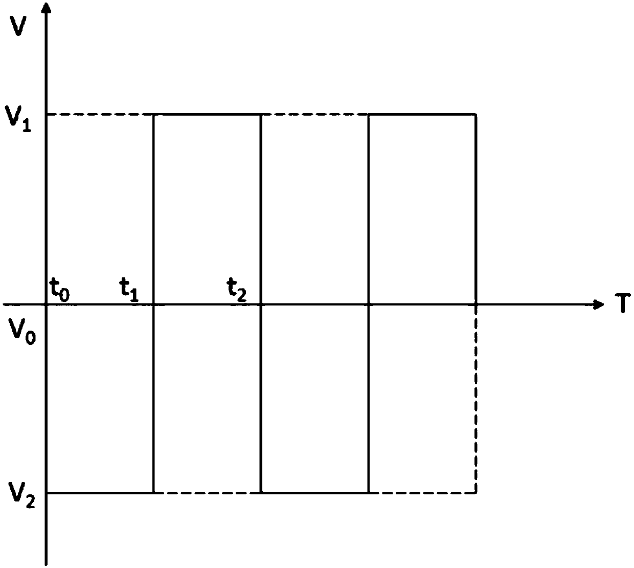
[0031] A method for generating electrowetting driving waveforms based on equal power, the power is expressed as:

[0032]

[0033] where g 1 (t) for t 0 to t 1 Waveform function during, g 2 (t) for t 1 to t 2 Waveform function during, v 1 A constant positive voltage connected to the pixel pole;

[0034] While maintaining the same power, where the driving stage, ie t 0 to t 1 stage driving voltage increases gradually, t 1 The voltage difference reaches the maximum value at any time;

[0035] Recovery phase, ie t 1 to t 2 stage, the voltage difference decreases to 0.

[0036] As an improvement of the technical solution, the driving stage waveform includes linear and parabolic shapes.

[0037] As an improvement of the technical solution, the waveform in the driving phase is a straight line wi...


PUM


Abstract

The invention discloses an electrowetting drive waveform generation method based on equipower. The electrowetting drive waveform generation method is characterized in that: power is shown as a formula in the description, wherein in the formula, g1 (t) is a waveform function during the period from t0 to t1, g2 (t) is a waveform function during the period from t1 to t2, and V1 is constant positive voltage connected to a pixel electrode; when the same power is maintained, the driving voltage is gradually increased at a driving stage, namely the stage from t0 to t1, and a voltage difference reaches the maximum value at t1 moment; and the voltage difference is reduced to 0 at a recovery stage, namely the stage from t1 to t2. The invention further discloses an electrowetting drive waveform generation system based on equipower. The electrowetting drive waveform generation system comprises a single chip microcomputer, an operational amplifier and a DAC0832, wherein an output end of the single chip microcomputer is connected with an input end of the DAC0832, and an output end of the DAC0832 is connected with an input end of the operational amplifier. The electrowetting drive waveform generation method and the electrowetting drive waveform generation device reduce the effective power of the drive waveforms, prolong the service life of electrowetting devices, adopt the gradually-changing waveforms, prevent printing ink from dividing the process of movement, and are widely used in the field of electrowetting.

Description

technical field [0001] The invention relates to the field of electrowetting, in particular to a method and system for generating electrowetting driving waveforms based on equal power. Background technique [0002] Electrowetting is a phenomenon in which the droplet is deformed and displaced by changing the voltage between the droplet and the insulating substrate, thereby changing the wettability of the droplet on the substrate, that is, changing the contact angle. [0003] Coat an oleophilic and hydrophobic insulating layer on the TFT electrode layer, use photolithographic materials to build a pixel wall on the insulating layer, and then coat a layer of black pigment oil film on the bottom of the pixel, place the entire substrate in water, and encapsulate it with the upper ITO glass Together they form the display. When the pixel is not powered on, the ink covers the entire bottom of the pixel, and the pixel presents the color of the ink at this time; when the lower TFT subs...

Claims


Application Information

Patent Timeline
Patent Type & Authority Patents(China)
IPC IPC(8): G09G3/34
CPCG09G3/348
Inventor 周国富马彩云赖树发刘先明易子川
Owner SHENZHEN GUOHUA OPTOELECTRONICS
Why Eureka
Try Eureka