Bypass air maintenance tire and pump assembly

a technology of air maintenance tire and pump assembly, which is applied in the direction of inflatable tyres, tire measurements, vehicle components, etc., can solve the problems of reducing vehicle braking and handling performance, reducing tire life, and reducing fuel economy, so as to improve traction

Active Publication Date: 2014-01-23
THE GOODYEAR TIRE & RUBBER CO
View PDF2 Cites 24 Cited by
  • Summary
  • Abstract
  • Description
  • Claims
  • Application Information

AI Technical Summary

Benefits of technology

[0029]“Sipe” means small slots molded into the tread elements of the tire that subdivide the tread surface and improve traction, s

Problems solved by technology

Accordingly, drivers must repeatedly act to maintain tire pressures or they will see reduced fuel economy, tire life and reduced vehicle braking and hand

Method used


Image

  • Bypass air maintenance tire and pump assembly
  • Bypass air maintenance tire and pump assembly
  • Bypass air maintenance tire and pump assembly

Examples


first embodiment

[0056]FIGS. 4A through 4C show an alternative embodiment in which the regulator valve assembly 78 is a 5-port inlet control configuration. It will be appreciated that alternative valve configurations may be employed in the practice of the invention and that the system is not dependent upon the use of a particular valve. In FIG. 4A, the valve is in the closed position in which air is not input into the tire cavity 26. FIG. 4B shows the valve in the open position with a tire clockwise rotational direction and air flow in the counter clockwise direction. FIG. 4C shows the valve in the open position during a counterclockwise tire rotation and clockwise air flow direction. As will be appreciated, in the valve shown in FIGS. 4A through 4C, air is admitted into the system through inlet port assembly 76 to the regulator valve assembly 78. Port assembly 76 includes a filter inlet port 80 and a filter body 82 housed within filter housing 84. Air passing through the filter 82 is directed via i...

second embodiment

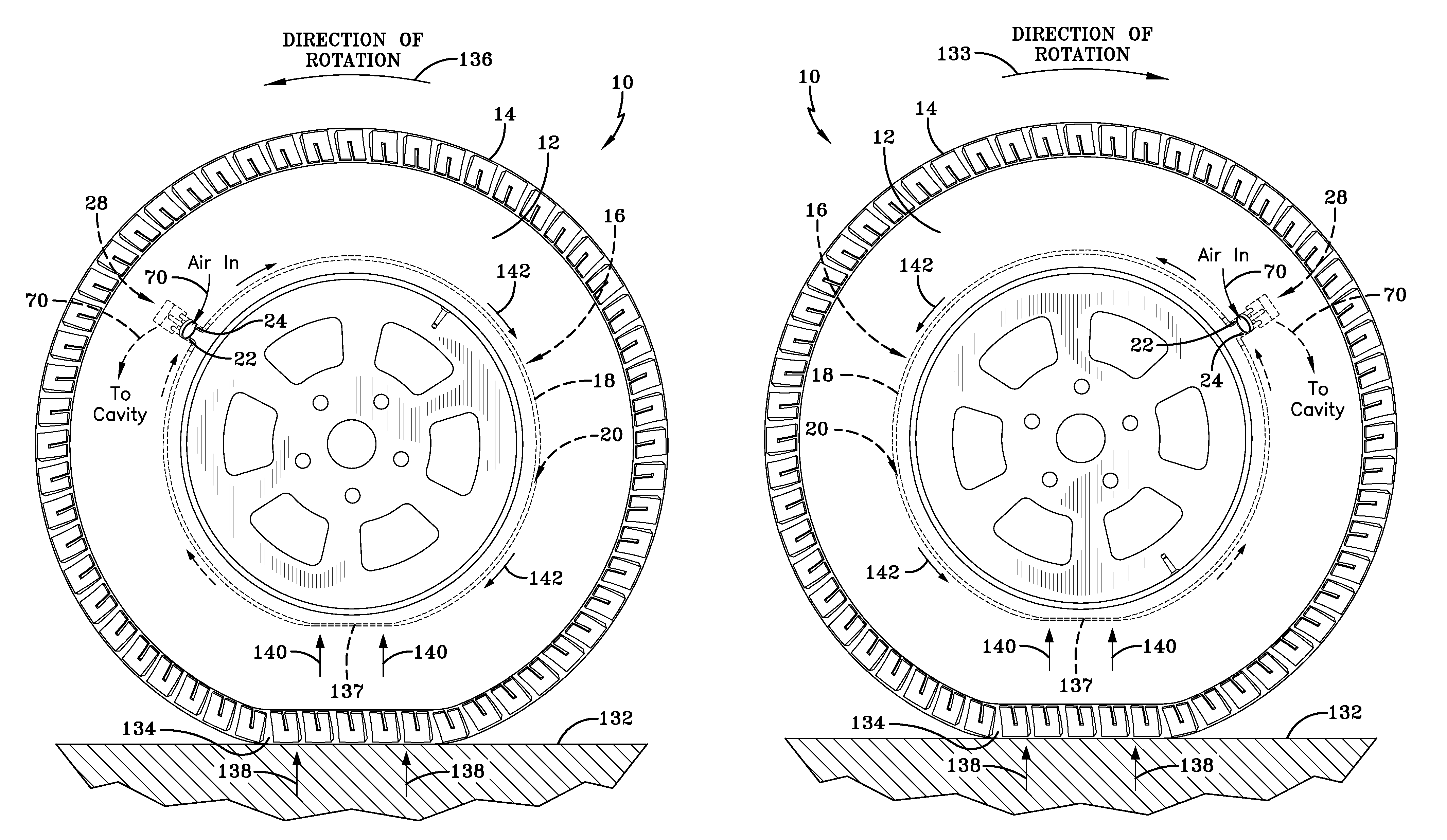
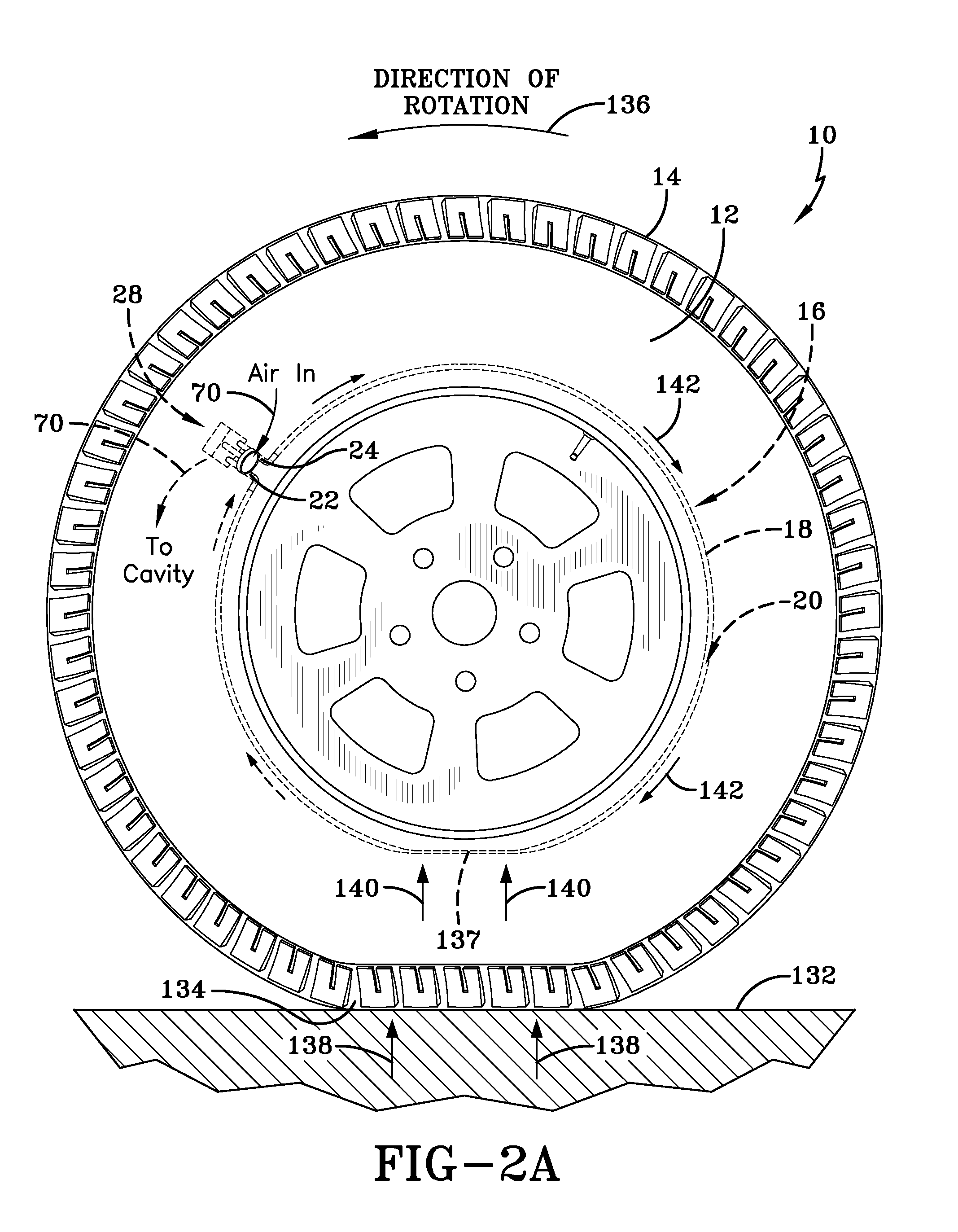
[0061]With reference to FIG. 5A, the cavity pressure is below Pset, causing the Bypass valve 120 to be closed. With the Bypass valve 120 closed, the operation of the Regulator and air passageway 18 proceeds as explained above in reference to the second embodiment under the conditions of FIG. 4B. FIG. 5A and FIG. 4B both represent a clockwise rotation of the tire, flow of air into (arrow 124) the system through filter inlet port 80, and a counterclockwise flow of air (arrow 126) within passageway 20. In FIG. 5B, for a counterclockwise rotation of the tire and a clockwise fill direction, the Bypass valve 120 continues to remain closed so long as the cavity pressure remains below Preg. Air flow (arrow 128) along the bypass conduit is thereby blocked by the closed valve 120. The air flow and fill direction in FIG. 5B thus proceeds as explained previously under the same analogous conditions under which the regulator of FIG. 4 operates. Air circulating in FIG. 5B in the clockwise directio...


PUM


Abstract

An air maintenance tire and pump assembly includes a pair of inline valves are positioned on respective opposite sides of an in-tire air passageway inlet junction and a pair of outlet valves positioned at a downstream side of a respective inline valve. A bypass valve is further provided extending between the downstream valve sides of the inline valves, the bypass valve operative to open and bypass the flow of inlet air through the outlet valves to the tire cavity in the event that a tire cavity pressure is greater than a preset pressure level and close when a tire cavity pressure is less than the preset pressure level.

Description

FIELD OF THE INVENTION[0001]The invention relates generally to air maintenance tires and, more specifically, to a tire and integrated pump assembly.BACKGROUND OF THE INVENTION[0002]Normal air diffusion reduces tire pressure over time. The natural state of tires is under inflated. Accordingly, drivers must repeatedly act to maintain tire pressures or they will see reduced fuel economy, tire life and reduced vehicle braking and handling performance. Tire Pressure Monitoring Systems have been proposed to warn drivers when tire pressure is significantly low. Such systems, however, remain dependant upon the driver taking remedial action when warned to re-inflate a tire to recommended pressure. It is a desirable, therefore, to incorporate an air maintenance feature within a tire that will maintain correct air pressure within the tire without a need for driver intervention to compensate for any reduction in tire pressure over time.SUMMARY OF THE INVENTION[0003]According to an aspect of the...

Claims


Application Information

Patent Timeline
IPC IPC(8): B60C29/04
CPCB60C29/04B60C23/123B60C23/135Y10T152/10495
Inventor GOBINATH, THULASIRAMLIN, CHENG-HSIUNGBENEDICT, ROBERT LEONCRANO, RICHARD NICHOLASO'DONNELL, ADAM JOSEPH
Owner THE GOODYEAR TIRE & RUBBER CO
Why Eureka
Try Eureka