
Vehicle lighting unit

a technology for vehicles and lighting components, applied in fixed installation, light and heating equipment, transportation and packaging, etc., can solve problems such as reducing light utilization efficiency, and achieve the effect of enhancing light utilization efficiency and effectively utilizing parts

Active Publication Date: 2014-01-23
STANLEY ELECTRIC CO LTD
View PDF2 Cites 11 Cited by
  • Summary
  • Abstract
  • Description
  • Claims
  • Application Information

AI Technical Summary

Benefits of technology

The present invention provides a vehicle lighting unit that can enhance the efficiency of using light by effectively utilizing the part of light emitted from the semiconductor light emitting element that cannot enter the light guide lens while being reflected by the light incident surface of the lens. This results in higher light utilization efficiency, allowing for the vehicle lighting unit to better serve as an automotive headlamp. Additionally, the invention eliminates the need for a dedicated reflection surface for forming an over-head sign light distribution pattern, reducing production costs.

Problems solved by technology

This can reduce the light utilization efficiency.

Method used


Image

  • Vehicle lighting unit
  • Vehicle lighting unit
  • Vehicle lighting unit

Examples


Embodiment Construction

[0033]A description will now be made below to vehicle lighting units of the presently disclosed subject matter with reference to the accompanying drawings in accordance with exemplary embodiments.

[0034]Note that in the present description, the directions of “front (forward),”“back (rear, rearward),”“left,”“right,”“up (high, above),” and “down (low, below)” mean the corresponding directions when viewed with respect to a vehicle lighting unit installed in a vehicle body of an automobile to project light forward of the vehicle body.

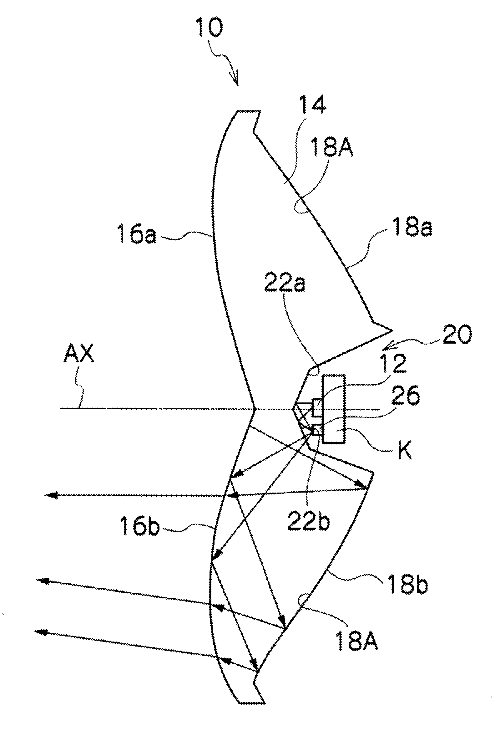
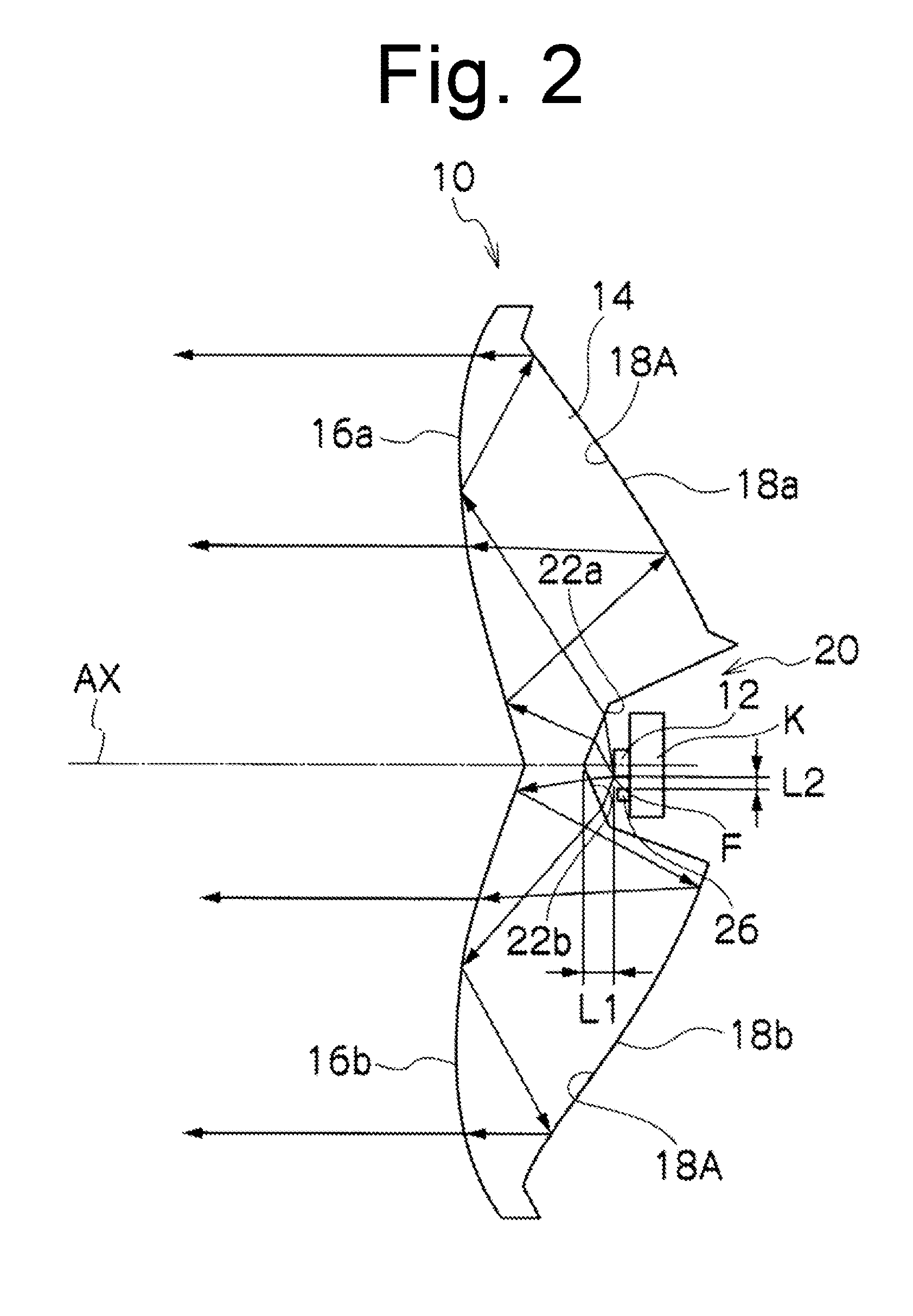
[0035]FIG. 2 is a cross-sectional view illustrating a vehicle lighting unit made in accordance with principles of the presently disclosed subject matter, vertically cut along a plane including its center axis. The drawing also shows light paths for light emitted from a semiconductor light emitting element and entering a light guide lens through its light incident surface.

[0036]At least one vehicle lighting unit 10 of the present exemplary embodiment can be p...


PUM


Abstract

A vehicle lighting unit is capable of enhancing the light utilization efficiency by effectively utilizing the part of light emitted from the semiconductor light emitting element that typically does not enter the light guide lens while being reflected by the light incident surface of the lens. The vehicle lighting unit can include a light guide lens a first surface configured to be disposed on a front side of a vehicle body, a second surface configured to be disposed on a rear side thereof and a recessed portion including a third surface; and a light emitting element disposed substantially at a reference point of the light guide lens. The second surface can include a reflection area extending from the recessed portion. The third surface can surround the semiconductor light emitting element, so that the light emitted from the semiconductor light emitting element can be incident on the third surface.

Description

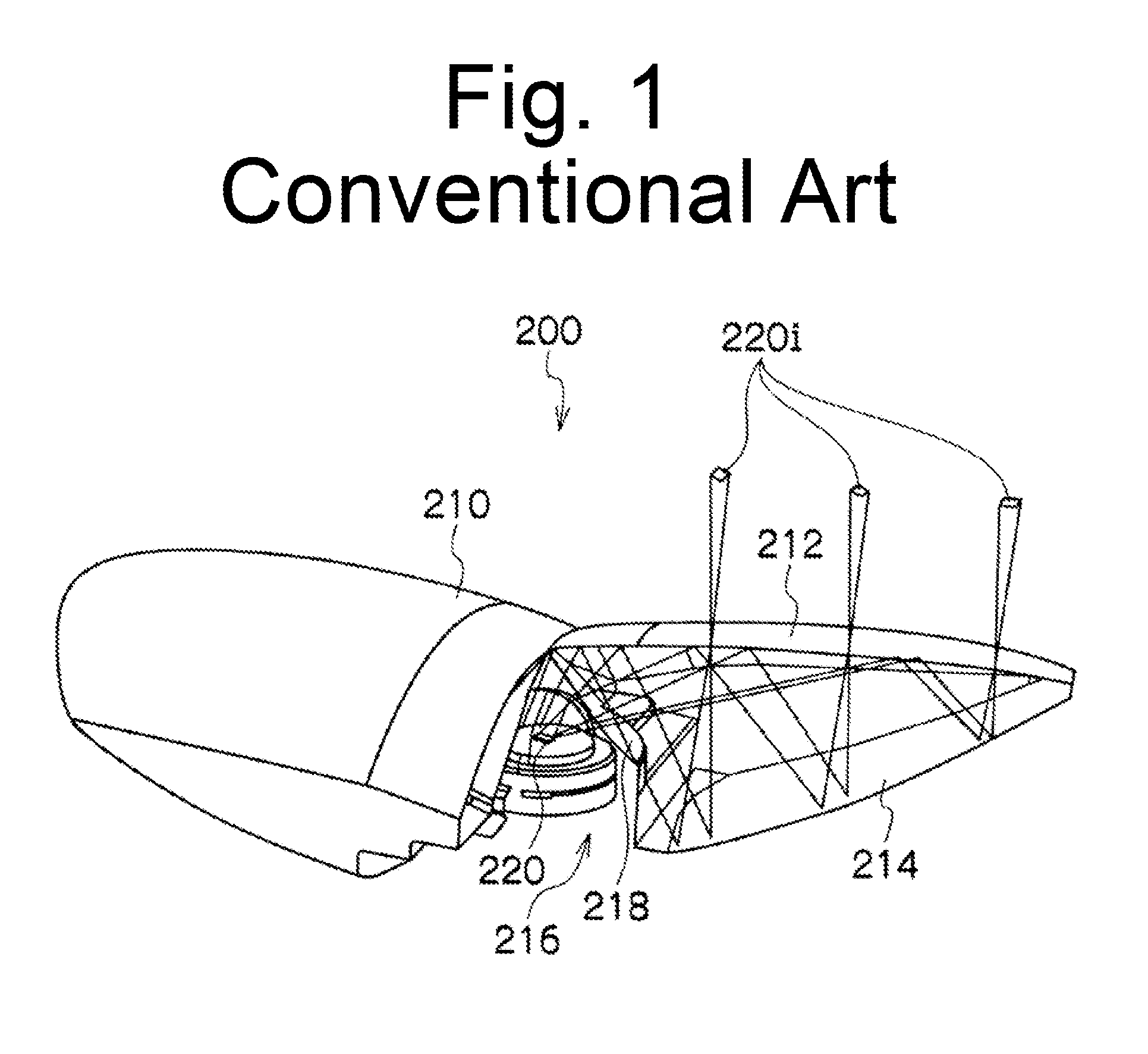
[0001]This application claims the priority benefit under 35 U.S.C. §119 of Japanese Patent Application No. 2012-162638 filed on Jul. 23, 2012, which is hereby incorporated in its entirety by reference.TECHNICAL FIELD[0002]The presently disclosed subject matter relates to a vehicle lighting unit, and in particular, to a vehicle lighting unit suitably used as an automotive headlamp, with a structure having a semiconductor light emitting element and a light guide lens in combination.BACKGROUND ART[0003]Conventionally, various automotive headlamps with a structure having a semiconductor light emitting element and a light guide lens in combination have been proposed, for example, such as those disclosed in U.S. Pat. No. 7,460,985 (Benitez et al.).[0004]FIG. 1 shows a perspective view of an automotive headlamp 200 which is disclosed in U.S. Pat. No. 7,460,985.[0005]As shown, the automotive headlamp 200 can include a light guide lens 210 and a semiconductor light emitting element 220. It i...

Claims


Application Information

Patent Timeline
IPC IPC(8): F21S8/10
CPCF21S48/13F21S41/143F21S41/151F21S41/153F21S41/155F21S41/16F21S41/176F21S41/24F21S41/285F21S41/321F21S41/322F21S41/365F21S41/37F21S41/43F21W2102/18F21S41/30
Inventor KONISHI, SADAYUKI
Owner STANLEY ELECTRIC CO LTD
Learn More