
Fixing Structure of Bone Screws and a Connecting Rod for a Minimally Invasive Surgery

a technology of bone screws and fixing structures, which is applied in the field of fixing structures of bone screws and connecting rods for minimally invasive surgery, can solve the problems of bone screws limiting the flexibility of movement and rotation, rigid sleeves cannot match with flexible columns well, and bone screws limit the options of treatment and corrective rehabilitation

Inactive Publication Date: 2014-01-23
WEI CHIH HSUAN
View PDF9 Cites 15 Cited by
  • Summary
  • Abstract
  • Description
  • Claims
  • Application Information

AI Technical Summary

Benefits of technology

The present invention is a fixing structure for bone screws and a connecting rod used in minimally invasive surgeries that allows for the generation of both rigid and flexible limitations. This structure provides flexibility for different treatments and corrective rehabilitations. The connection between the rigid sleeve and flexible column is simple, saving operation time, and the rigid sleeve is easy to control design and production cost. The use of a rigid sleeve and flexible column reduces the size of the implant needed and simplifies the fixation process.

Problems solved by technology

A conventional fixing structure of bone screws and a connecting rod is made of rigid material, so between the bone screws lacks a flexible bending and rotating ability, and the spine can not bend or rotate flexibly, thus limiting applicable options in treatment and corrective rehabilitations.
Although the convention fixing structure of the bone screws and the connecting rod can lock and position the spines, the bone screws limit the flexibility in a movement and a rotation.
Besides, the rigid sleeve can not match with the flexible column well.

Method used


Image

  • Fixing Structure of Bone Screws and a Connecting Rod for a Minimally Invasive Surgery
  • Fixing Structure of Bone Screws and a Connecting Rod for a Minimally Invasive Surgery
  • Fixing Structure of Bone Screws and a Connecting Rod for a Minimally Invasive Surgery

Examples


Embodiment Construction

[0023]The present invention will be clearer from the following description when viewed together with the accompanying drawings, which show, for purpose of illustrations only, the preferred embodiment in accordance with the present invention.

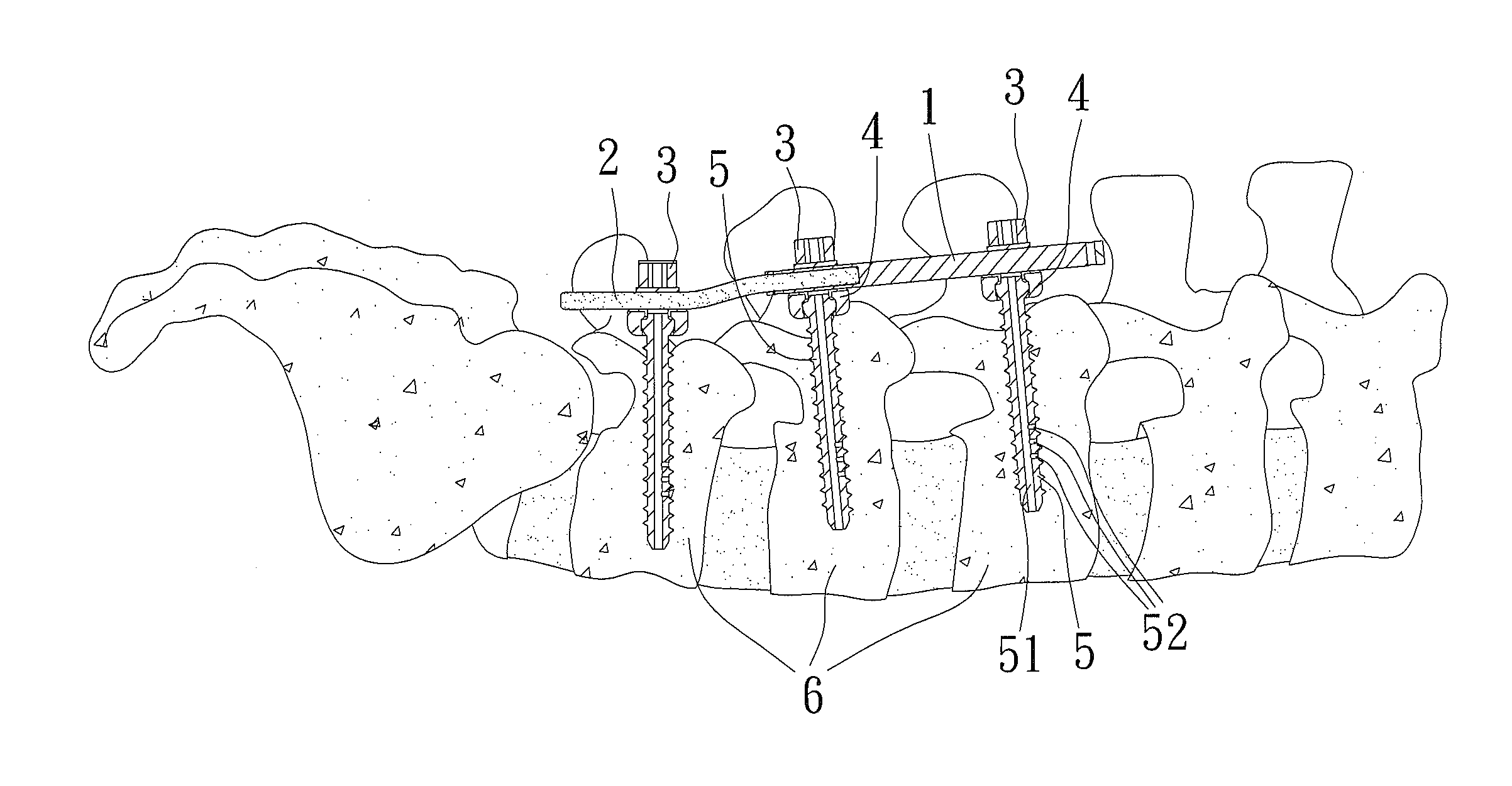
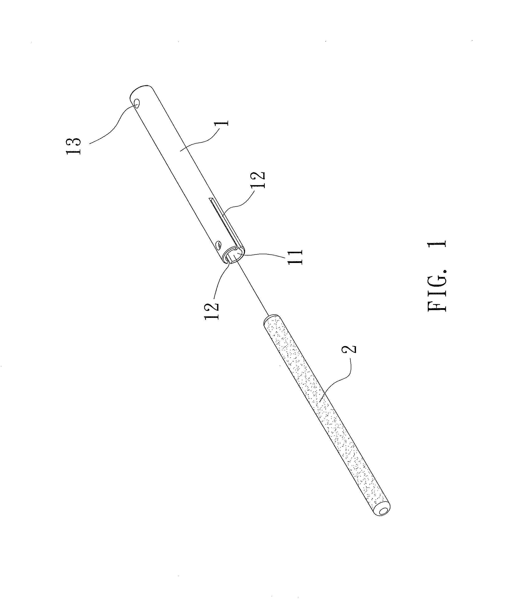
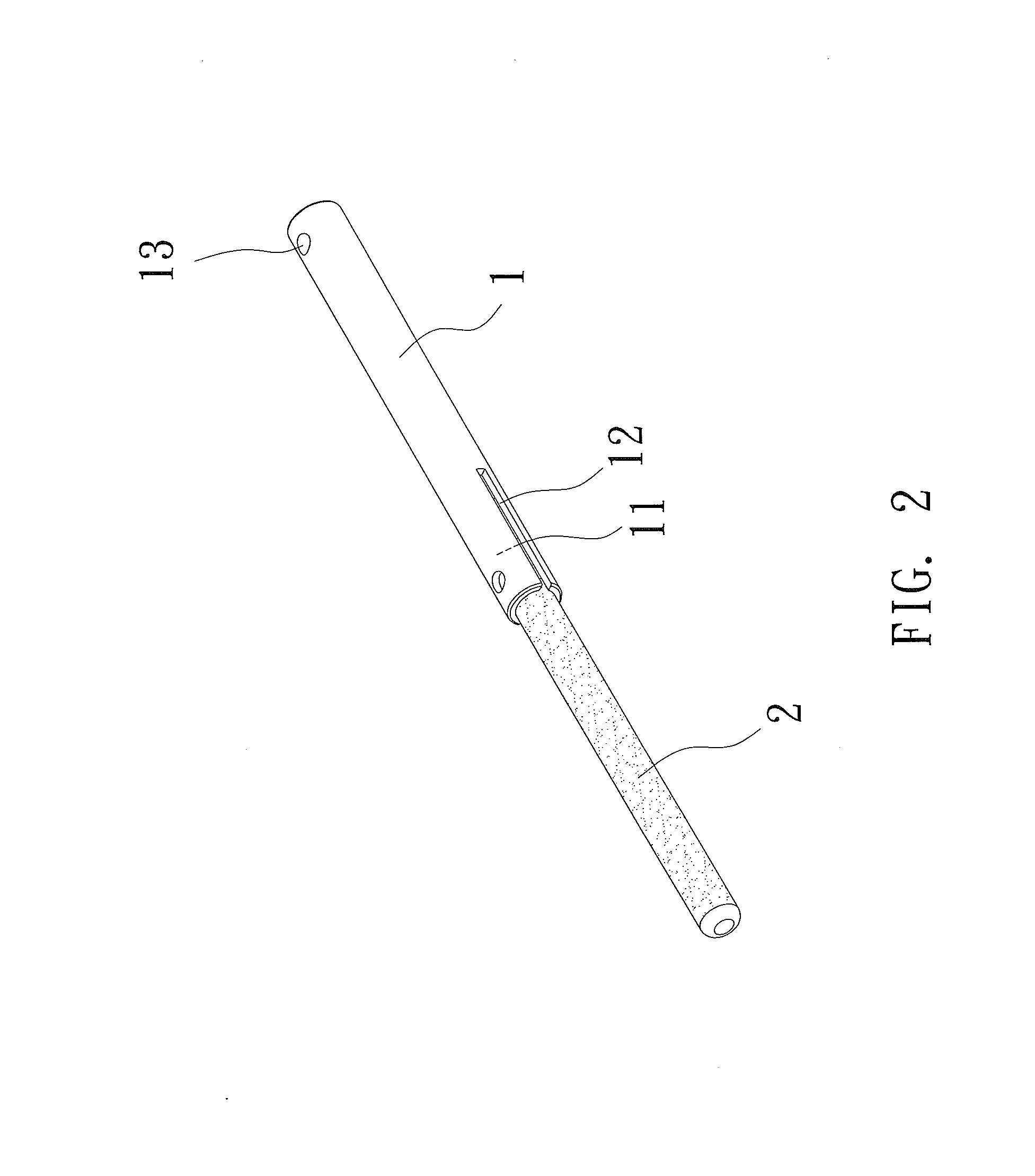
[0024]Referring to FIGS. 1-3, a fixing structure of bone screws and a connecting rod for a minimally invasive surgery according to a preferred embodiment of the present invention comprises:

[0025]a rigid sleeve 1 having a receiving space 11, two slots 12, and a through hole 13, wherein the receiving space 11 and the through hole 13 are defined on two ends of the rigid sleeve 1, and the two slots 12 are formed on two opposite sides of an outer wall of the rigid sleeve 1 and communicate with the receiving space 11, the rigid sleeve 1 is made of metal material;

[0026]a flexible column 2 being circular and retained in the receiving space 11 of the rigid sleeve 1 and being made of plastic, rubber, high-density foam, or silicone.

[0027]Referring further t...


PUM


Abstract

A fixing structure of bone screws and a connecting rod for a minimally invasive surgery contains: a rigid sleeve having a receiving space, two slots, and a through hole, the receiving space and the through hole being defined on two ends of the rigid sleeve, and the two slots being formed on two opposite sides of an outer wall of the rigid sleeve and communicate with the receiving space; a flexible column being circular and retained in the receiving space of the rigid sleeve. Thereby, a complete rigid limitation and partial flexible limitations generate between at least one bone screw, hence only a tiny opening is cut in the minimally invasive surgery to facilitate surgery recovery and to lower infection risk.

Description

BACKGROUND OF THE INVENTION[0001]1. Field of the Invention[0002]The present invention relates to a fixing structure of bone screws and a connecting rod for a minimally invasive surgery which allows fixing a rigid sleeve and a flexible column to generate a complete rigid limitation and partial flexible limitations.[0003]2. Description of the Prior Art[0004]A conventional fixing structure of bone screws and a connecting rod is made of rigid material, so between the bone screws lacks a flexible bending and rotating ability, and the spine can not bend or rotate flexibly, thus limiting applicable options in treatment and corrective rehabilitations.[0005]Although the convention fixing structure of the bone screws and the connecting rod can lock and position the spines, the bone screws limit the flexibility in a movement and a rotation. Besides, the rigid sleeve can not match with the flexible column well.[0006]The present invention has arisen to mitigate and / or obviate the afore-described...

Claims


Application Information

Patent Timeline
IPC IPC(8): A61B17/70
CPCA61B17/7019A61B17/7031A61B17/7032A61B17/7037
Inventor WEI, CHIH-HSUAN
Owner WEI CHIH HSUAN
Learn More