Sucker with Optimum Suction Attachment Effect

a suction attachment and suction tube technology, applied in the field of suction tubes, to achieve the effect of reducing the existing air, reducing the leakage of vacuum, and increasing the air tightness

Active Publication Date: 2014-01-30
TRU MILES HARDWARE
View PDF6 Cites 20 Cited by
  • Summary
  • Abstract
  • Description
  • Claims
  • Application Information

AI Technical Summary

Benefits of technology

The present invention provides a sucker with a rough suction layer that has multiple negative pressure zones to increase the negative pressure, decrease air, and reduce vacuum leak. This improves the air-tightness between the rough suction layer and the attached face, allowing for a tight attachment. The sucker is designed for an optimum airtight suction state, ensuring accurate attachment to even unsmooth or cracked faces. Overall, the invention improves the efficiency and reliability of sucking in various applications.

Problems solved by technology

However, when the attached face is uneven or unsmooth, the sucker body 10 cannot be attached to the attached face closely and tightly, so that the sucker body 10 is easily detached from the attached face during a long-term utilization.

Method used


Image

  • Sucker with Optimum Suction Attachment Effect
  • Sucker with Optimum Suction Attachment Effect
  • Sucker with Optimum Suction Attachment Effect

Examples


Embodiment Construction

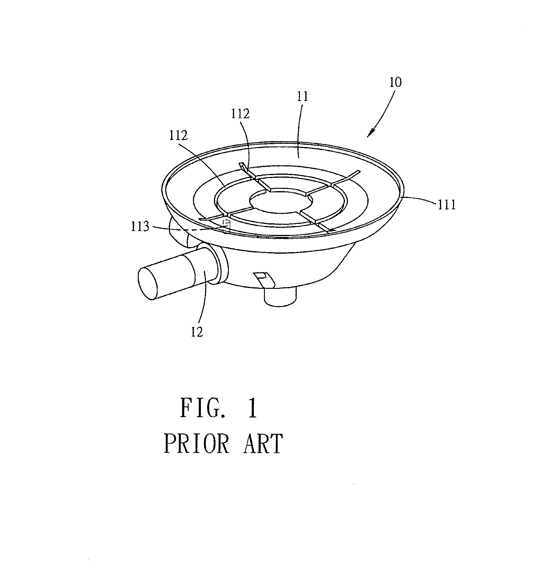
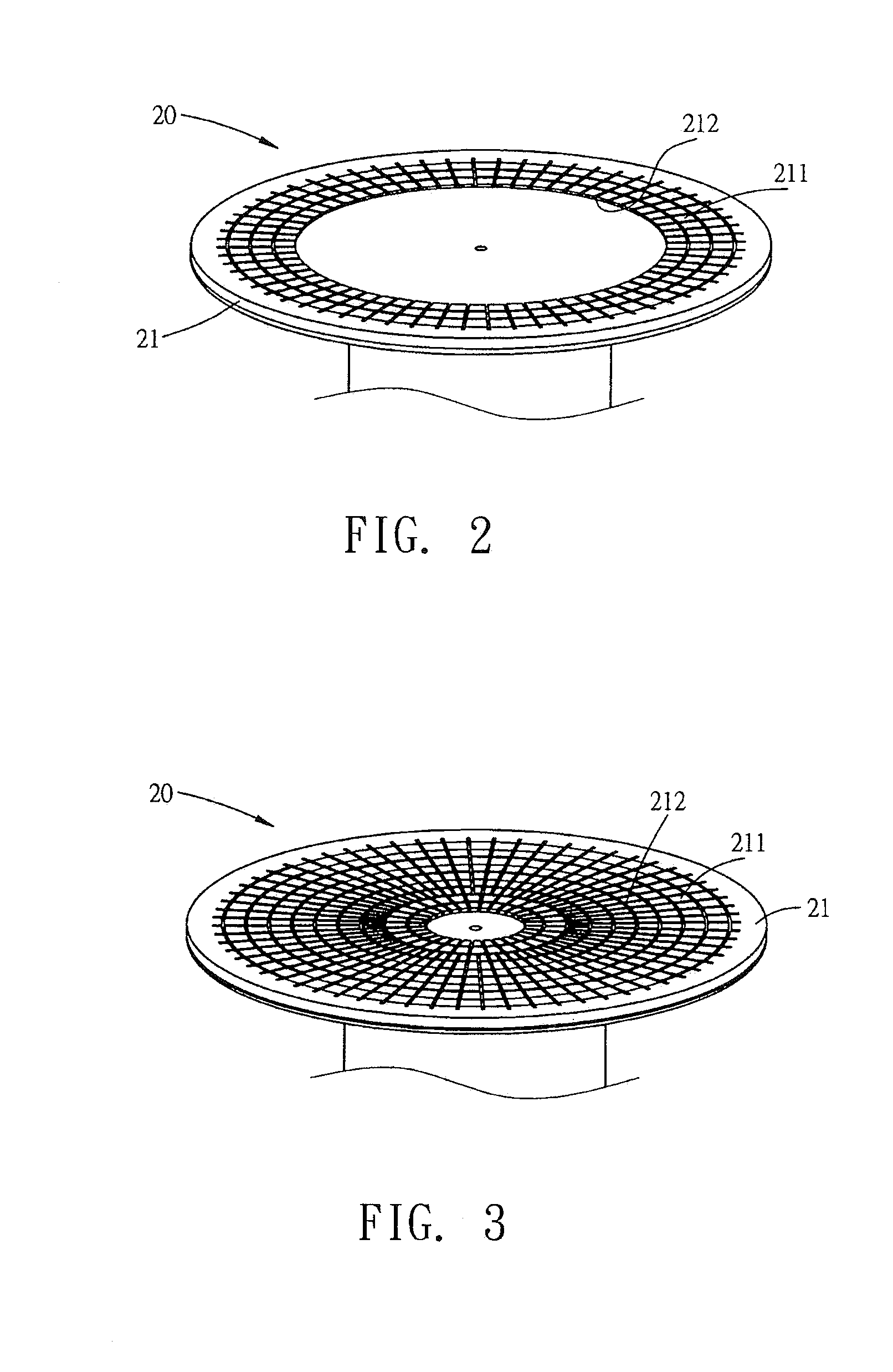
[0021]Referring to the drawings and initially to FIGS. 2 and 3, a sucker in accordance with the preferred embodiment of the present invention comprises a sucker body 20. The sucker body 20 includes a rough suction layer 21. The rough suction layer 21 of the sucker body 20 has a planar shape and has a slightly adhesive feature. The rough suction layer 21 of the sucker body 20 includes a plurality of protrusions 211 which are juxtaposed to each other closely, and a plurality of grooves 212 defined between the protrusions 211. The protrusions 211 of the rough suction layer 21 are arranged in an annular shape. Preferably, the protrusions 211 of the rough suction layer 21 are distributed and extended through a peripheral surface of the rough suction layer 21 as shown in FIG. 2 or a whole circumferential surface of the rough suction layer 21 as shown in FIG. 3.

[0022]In practice, when the rough suction layer 21 of the sucker body 20 presses an attached face “A” (see FIG. 6) and is disposed...


PUM


Abstract

A sucker includes a sucker body having a rough suction layer which includes a plurality of protrusions which are juxtaposed to each other closely, and a plurality of grooves defined between the protrusions. When the rough suction layer presses an attached face and is disposed at a negative pressure state, the sucker body is pressed toward the attached face by a normal force from the ambient air, so that the rough suction layer is compressed, and the grooves form multiple independent negative pressure or vacuum zones, to increase a negative pressure of the rough suction layer, to decrease air existing in the rough suction layer, and to reduce a vacuum leak in the rough suction layer, so as to increase an air-tightness between the rough suction layer and the attached face.

Description

BACKGROUND OF THE INVENTION[0001]1. Field of the Invention[0002]The present invention relates to an attachment device and, more particularly, to a sucker for attaching an article to an attached face, such as a wall, plane and the like.[0003]2. Description of the Related Art[0004]A conventional sucker in accordance with the prior art shown in FIG. 1 comprises a sucker body 10 and an air extraction mechanism 12 connected with the sucker body 10. The sucker body 10 has a side provided with an attachment portion 11 which has a periphery provided with an annular flange 111. The attachment portion 11 of the sucker body 10 has a surface provided with a plurality of slits 112 with circular or cruciform shape. The attachment portion 11 of the sucker body 10 has an interior provided with an air channel 113 connected between the slits 112 and the air extraction mechanism 12. In operation, when the flange 111 of the sucker body 10 abuts an attached face, the air extraction mechanism 12 is press...

Claims


Application Information

Patent Timeline
Patent Type & Authority Applications(United States)
IPC IPC(8): F16B47/00
CPCF16B47/006F16B47/00A47G1/17
Inventor CHEN, KUEI-I
Owner TRU MILES HARDWARE
Why Eureka
Try Eureka