Swirling flow premixing type burner

A flow premixing and burner technology, which is applied in the direction of burners, gas fuel burners, combustion methods, etc., can solve the problem of increased pure oxygen consumption of the secondary reformer, lower reformer furnace temperature, and increased energy consumption for methane conversion, etc. problems, to achieve the effect of improving heat transfer characteristics, increasing heat transfer rate, and reducing smoke emission

Inactive Publication Date: 2013-01-16
SICHUAN UNIV
View PDF5 Cites 8 Cited by
  • Summary
  • Abstract
  • Description
  • Claims
  • Application Information

AI Technical Summary

Problems solved by technology

The disadvantage of this kind of burner is that the amount of combustion air is large and the flame is longer
With the reduction of the calorific value of the gas, a large amount of air takes away the heat of the furnace, resulting in a decrease in the temperature of the reforming furnace, a decrease in the methane conversion rate, an increase in the pure oxygen consumption of the secondary reformer, and a sharp increase in the energy consumption of methane conversion

Method used


Image

  • Swirling flow premixing type burner
  • Swirling flow premixing type burner
  • Swirling flow premixing type burner

Examples


Embodiment

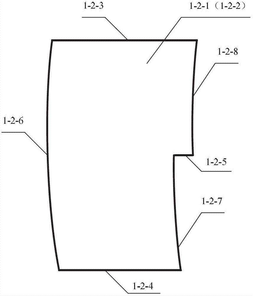
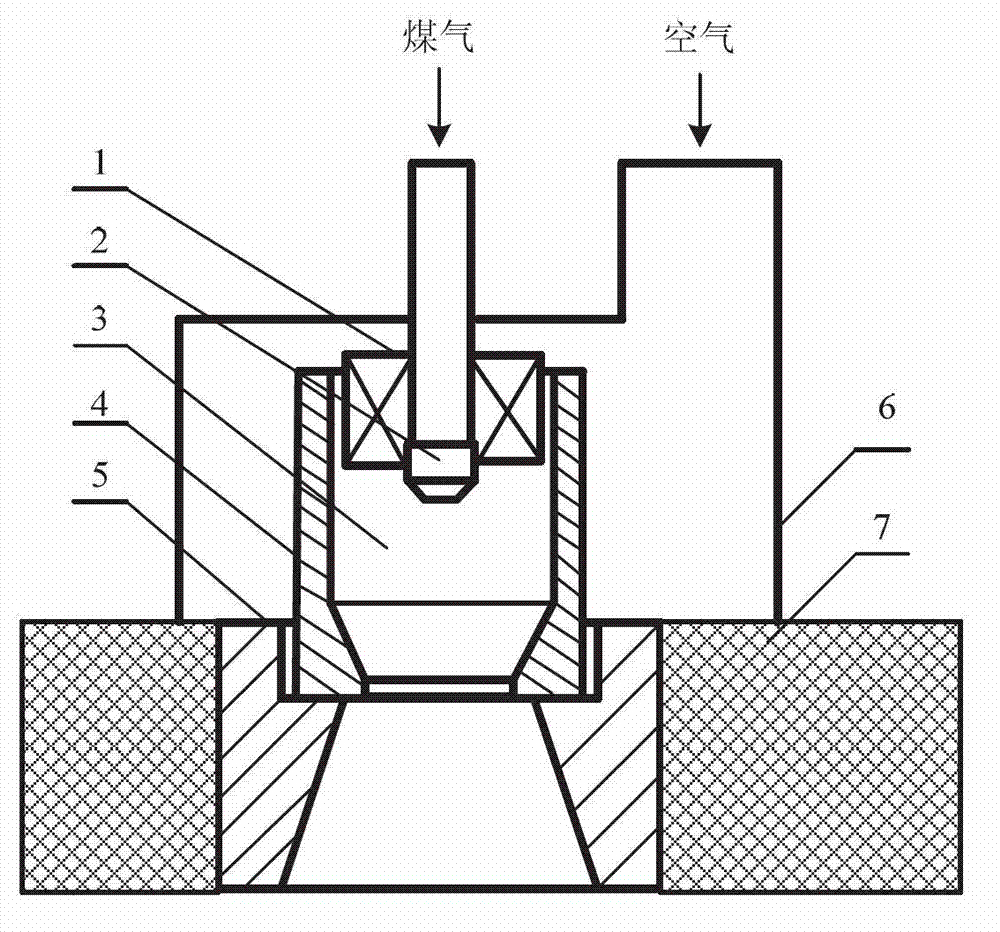
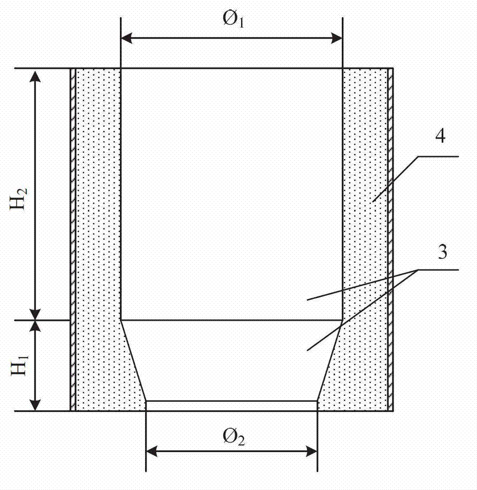
[0027] In this embodiment, the structure of the swirl premix burner is as follows figure 1 As shown, it is composed of the first burner brick 5, the second burner brick 4, the combustion air chamber 6, the air cyclone 1 and the gas nozzle 2; the shape and structure of the second burner brick 4 are as follows figure 2 As shown, its outer contour shape is cylindrical, and its center is provided with a swirl premixing chamber 3, which is a combination of a cylindrical hole and a truncated conical hole on the same center line, and the truncated conical hole Below the cylindrical hole, the height H of the cylindrical hole 2 : Height H of the frustoconical hole 1 = 3: 1; the diameter of the cylindrical hole? 1 : The diameter of the lower end of the truncated cone hole? 2 =1.4:1; the shape and structure of the first burner 5 are as figure 1 As shown, its outer contour shape is cylindrical, and the upper section of its central hole matches the outer contour shape and size of th...


PUM


Abstract

The invention discloses a swirling flow premixing type burner. The swirling flow premixing type burner comprises a first burner brick, a second burner brick, a burning-supporting air chamber, an air swirler and a fuel gas nozzle, wherein a central hole is formed in the first burner brick; an upper section of the central hole is matched with the shape of the exterior outline and the dimension of the second burner brick; a lower section of the central hole is a cone-shaped hole with a large upper end aperture and small lower end aperture; a premixing chamber is arranged in a central part of the second burner brick; the fuel gas nozzle is a swirling flow nozzle and consists of a nozzle body and a gas inlet pipe which is connected with the nozzle body; the first burner brick is arranged on a furnace body; the second burner brick is arranged in the first burner brick; the air swirler is positioned at the inlet of the premixing chamber arranged in the second burner brick; the fuel gas nozzle is combined with the air swirler; the nozzle body of the fuel gas nozzle is positioned below the air swirler; and the burning-supporting air chamber is arranged on the furnace body.

Description

technical field [0001] The invention belongs to the technical field of combustion, and in particular relates to a high-efficiency and energy-saving burner used in industrial furnaces (coal-to-ammonia-methane reformer, purge gas, combustible tail gas recovery furnace, etc.). Background technique [0002] Due to its high operating temperature and high fuel consumption, industrial furnaces are often the processing units with the highest energy consumption in factories. The progress of industrial furnace energy-saving technology is mainly reflected in two aspects: one is the recovery of waste heat from flue gas, which is used as a heating medium; the other is to optimize the combustion process and reduce the amount of smoke. The former has been accepted by the industry, and most industrial furnaces are equipped with waste heat recovery devices. The latter has not been paid attention to by the industry. Many industrial furnaces still use backward combustion technology. The amoun...

Claims


Application Information

Patent Timeline
Patent Type & Authority Applications(China)
IPC IPC(8): F23D14/02F23D14/46F23D14/70
Inventor 叶世超祝杰张莉
Owner SICHUAN UNIV
Why Eureka
Try Eureka