
Wall-mountable luminaire and associated systems and methods

a wall-mounted luminaire and luminaire technology, applied in the field of low-profile wall-mounted luminaires, can solve the problems of existing wall-mounted lighting devices, non-uniform light intensities, and design problems, and achieve the effect of promoting both ease of use and flexibility of installation

Active Publication Date: 2014-01-30
LIGHTING SCI GROUP
View PDF42 Cites 24 Cited by
  • Summary
  • Abstract
  • Description
  • Claims
  • Application Information

AI Technical Summary

Benefits of technology

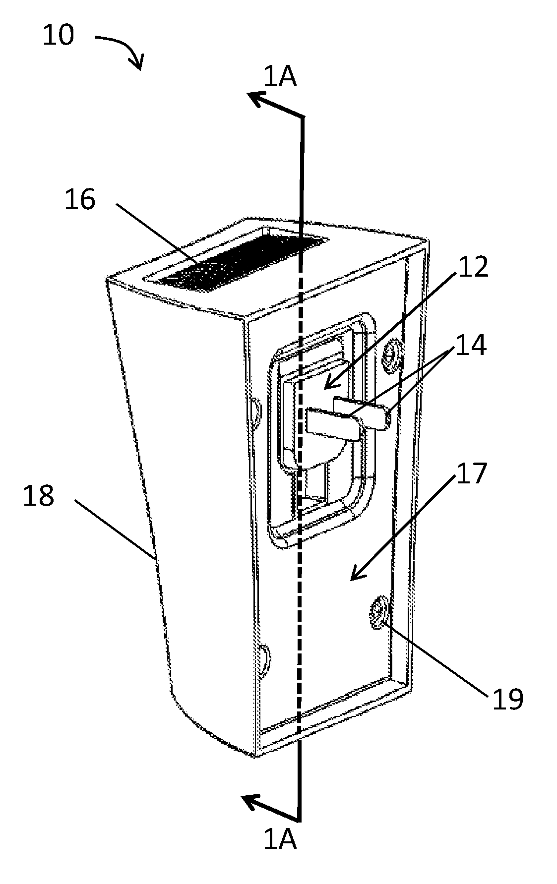
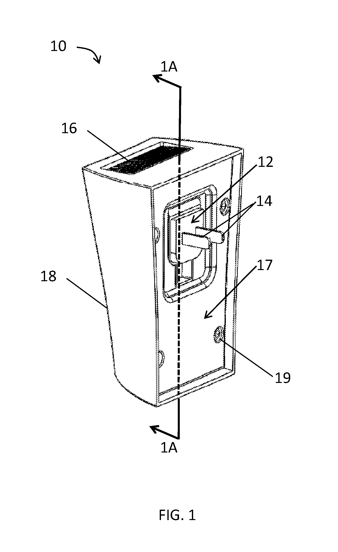
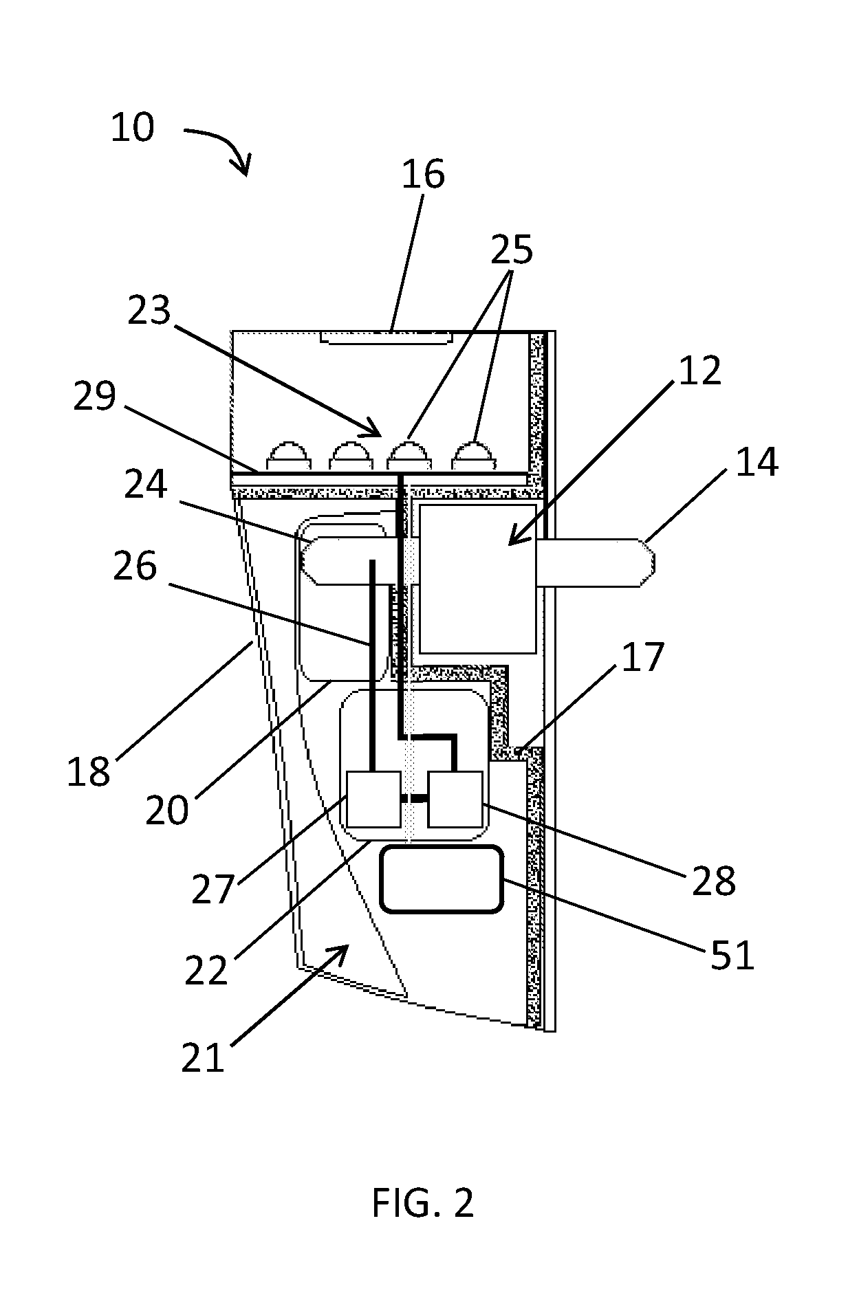
The present invention is related to a luminaire that can be used to produce remotely-configurable wall-wash illumination. This luminaire is designed to be less obtrusive and more aesthetically desirable than traditional lighting devices. It supports various types of input power, making it easier and safer to install. Additionally, it supports remote operation, promoting ease of use and flexibility of installation compared to traditional lighting devices. The luminaire includes power delivery components, lighting generation components, and mechanical support components.

Problems solved by technology

While presently available ceiling-, floor-, or wall-mounted wall-wash lighting devices are capable of illuminating wall surfaces, problems in design still remain.
Most of the existing wall-wash lighting devices provide an illumination pattern of non-uniform light intensities when projected upon vertical wall surfaces.
Specifically, existing wall-wash lighting devices suffer from strong illumination near the light source and a weakening, parabolic-shaped lighting pattern as the projection distance from the light source increases.
Use of light emitting diodes (LEDs) in the light source of a wall-wash lighting device may compound the problem of non-uniform illumination.
As a result, even use of a globe-shaped optic to shape the emissions of an LED may not produce an equal distribution of light.
However, this design trade-off often results in a wall-wash lighting device that may deliver acceptable illumination, but that also presents an obtrusive and aesthetically unappealing appearance as installed.
Powering wall-mount lighting devices also may pose challenges for both the designer and manufacturer.
Additionally, a manufacturer's choice of light sources also places limits on power circuitry present in a lamp design.
Too little current and voltage may result in little or no light.
Too much current and voltage can damage the light-emitting junction of the LED.
However, such radio receivers typically require an antenna located within the lighting device.
The attenuation of the signal may result in a substantially decreased range in which the LED-based lighting device may communicate with the remote control, thereby decreasing the practicality and deployment flexibility of the lighting device.
Such visible conductors are not aesthetically pleasing for wall-mount applications.
A need exists for an LED-based wall-wash lighting device that may provide a large and substantially uniform wall-wash illumination pattern, while at the same time presenting an unobtrusive and clean appearance when installed.

Method used


Image

  • Wall-mountable luminaire and associated systems and methods
  • Wall-mountable luminaire and associated systems and methods
  • Wall-mountable luminaire and associated systems and methods

Examples


Embodiment Construction

[0035]The present invention will now be described more fully hereinafter with reference to the accompanying drawings, in which preferred embodiments of the invention are shown. This invention may, however, be embodied in many different forms and should not be construed as limited to the embodiments set forth herein. Rather, these embodiments are provided so that this disclosure will be thorough and complete, and will fully convey the scope of the invention to those skilled in the art. Those of ordinary skill in the art realize that the following descriptions of the embodiments of the present invention are illustrative and are not intended to be limiting in any way. Other embodiments of the present invention will readily suggest themselves to such skilled persons having the benefit of this disclosure.

[0036]Although the following detailed description contains many specifics for the purposes of illustration, anyone of ordinary skill in the art will appreciate that many variations and a...


PUM


Abstract

A wall-mountable luminaire may include interchangeable adapter plugs having first and second male connectors, the first of which connects electrically and mechanically to an external electrical socket, and the second of which connects electrically and mechanically to an on-board multi-standard socket. A power supply may detect a plurality of electrical power types received from the multi-standard socket, and may condition that input power to drive LEDs. Remote computing devices may transmit control data wirelessly to direct a controller to selectively operate the LEDs to form a modified distribution pattern. A housing assembly may support wall mounting of the luminaire, and trim assembly may define a cavity that provides aesthetic and protective cover for the components carried by the housing assembly. A method aspect of the invention details steps for operating the luminaire.

Description

RELATED APPLICATIONS[0001]This application claims the benefit under 35 U.S.C. §119(e) of U.S. Provisional Patent Application Ser. No. 61 / 643,687 filed on May 7, 2012 and titled Wall Mountable Light and Associated Methods, the entire contents of which are incorporated herein by reference.FIELD OF THE INVENTION[0002]The present invention relates to the field of lighting and, more specifically, to low-profile wall-wash luminaires, and associated systems and methods.BACKGROUND OF THE INVENTION[0003]Lighting designed to illuminate vertical surfaces such as walls typically is called wall-wash lighting. Wall-wash lighting devices commonly include a light source, a power supply, and a mounting mechanism. A wall-wash lighting device mounted above a substantially vertical surface to be illuminated is classified as a down light. A wall-wash lighting device positioned below a substantially vertical surface to be illuminated is called an up light. While presently available ceiling-, floor-, or w...

Claims


Application Information

Patent Timeline
Patent Type & Authority Applications(United States)
IPC IPC(8): F21V23/06H05B37/02
CPCH05B37/0272F21V23/06F21S8/035F21S9/024H05B47/19
Inventor MAXIK, FREDRIC S.BARTINE, DAVID E.OOSTDYK, MARK ANDREWREGAN, MATTHEWWIDJAJA, ADDY S.
Owner LIGHTING SCI GROUP
Learn More