Passive power factor correction circuit

a technology of power factor and correction circuit, applied in the direction of power conversion system, climate sustainability, efficient power electronics conversion, etc., can solve the problems of equipment with lower power factor not only waste energy but also waste energy, and achieve the effect of suppressing the ripple of input curren

Active Publication Date: 2014-01-30
IND TECH RES INST
View PDF6 Cites 12 Cited by
  • Summary
  • Abstract
  • Description
  • Claims
  • Application Information

AI Technical Summary

Benefits of technology

[0008]In one embodiment, the present disclosure provides a passive power factor correction circuit comprising: a filtering device being used for decreasing high order harmonic of an input current; a resonance device being coupled to the filtering device for controlling operation time of the input current; and a suppression device being coupled to the resonance device for suppressing ripple of the input current.

Problems solved by technology

However, the operation point designed by the passive power factor correction circuit is easily affected by the input voltage, input voltage frequency and output power, so as to affect the result of power factor correction.
Furthermore, only if the input voltage is higher than the capacitor voltage, the output capacitor is charged by the input power so as to decrease the charge time of the capacitor, and the turn-on time of the rectified diode gets shorter with the charge time and the peak value of the conductive current increases, causing that the power factor is decreased and the input current waveform is distorted.
The equipments with lower power factor not only waste energy but also increase unnecessary reactive power required by the electricity company.
Owing to the output filter capacitor Cdc existence, it causes that the input current contains large amount of harmonic distortion so as to lower the power factor and seriously distort current total harmonic distortion.
Since the inductor composed of silicon steel sheet is bulky and heavy, and the highest power factor of the circuit is only up to around 75%.
Although the bridge rectified circuit of the conventional passive power factor correction circuit has simple and durable advantages, its poor performance does not meet nowadays application needs.
However, the active power factor correction circuit requires extra control circuit and the price, electromagnetic noise and robustness thereof are nowhere near as good as the passive power factor correction circuit.

Method used


Image

  • Passive power factor correction circuit
  • Passive power factor correction circuit
  • Passive power factor correction circuit

Examples


Embodiment Construction

[0021]In the following detailed description, for purposes of explanation, numerous specific details are set forth in order to provide a thorough understanding of the disclosed embodiments. It will be apparent, however, that one or more embodiments may be practiced without these specific details. In other instances, well-known structures and devices are schematically shown in order to simplify the drawing.

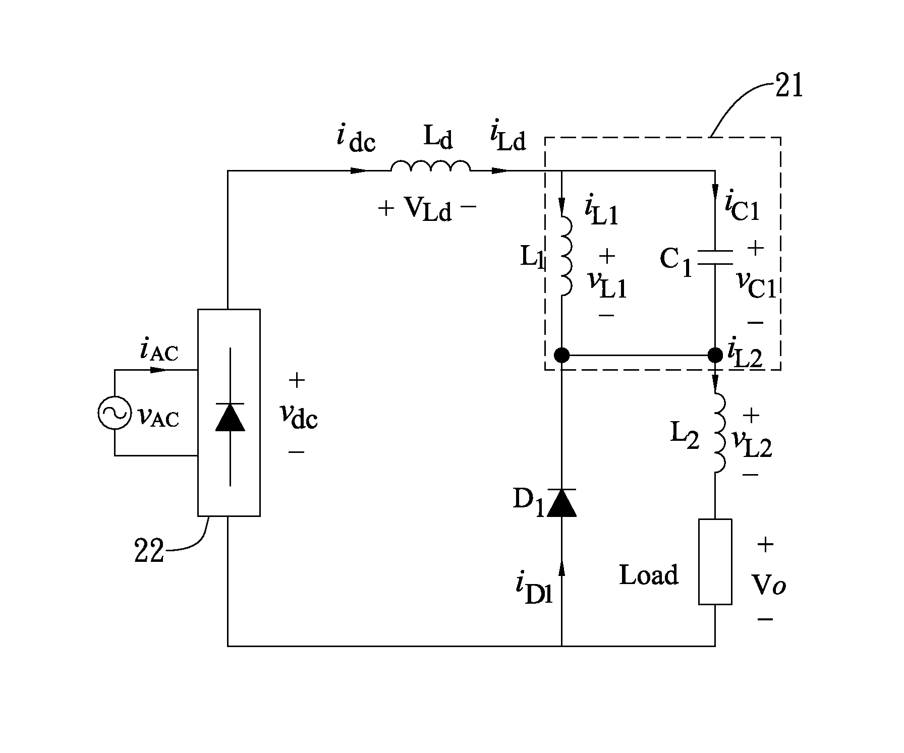
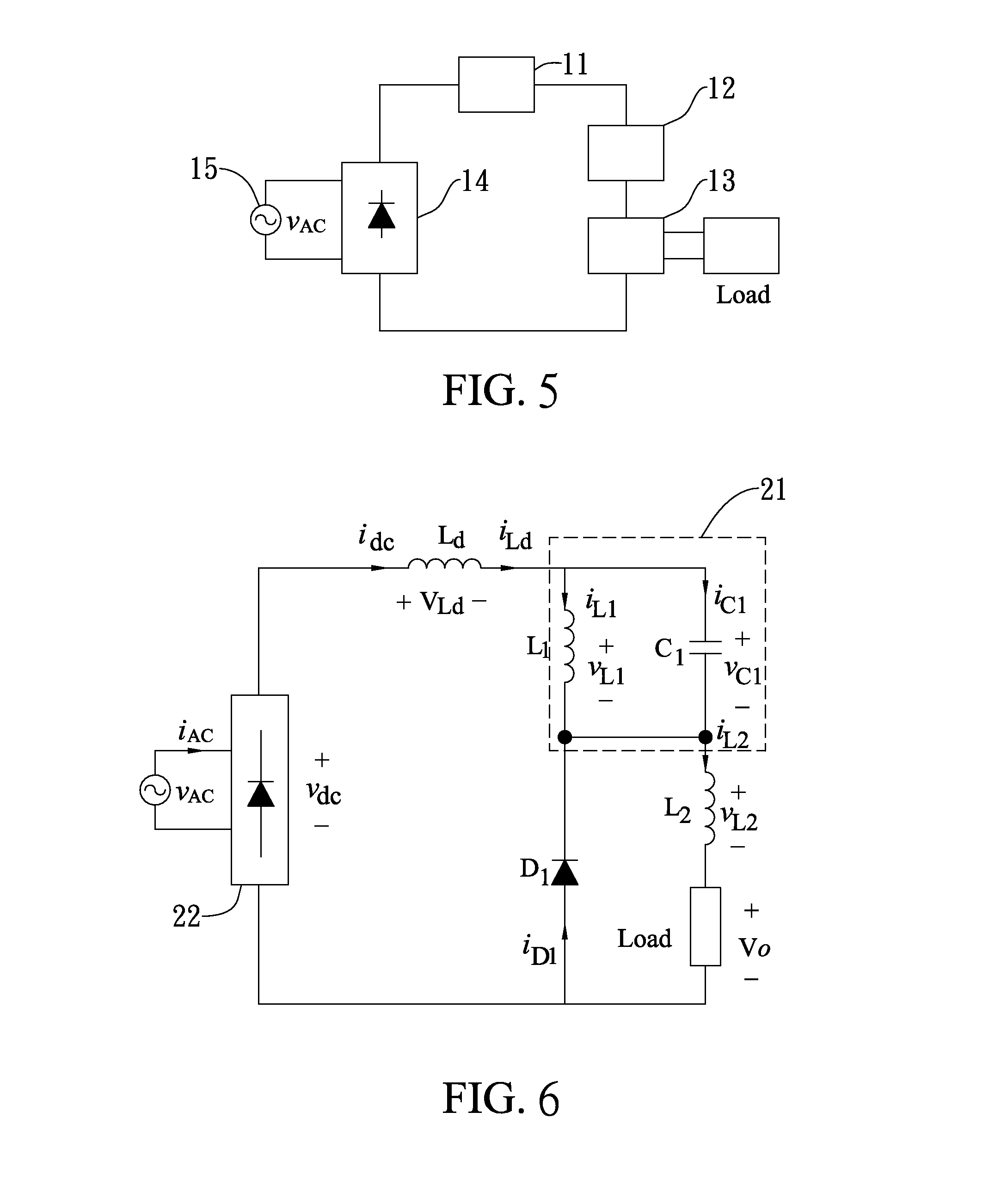
[0022]FIG. 5 shows a passive power factor correction circuit according to one embodiment of the present disclosure. The passive power factor correction circuit includes a filtering device 11, a resonance device 12 and a suppression device 13. The filtering device 11 is used for reducing high-order harmonics of an input current, and also includes a filter inductor. Further, the input current is delayed by the filtering device 11 for a period time, and then the input current starts to flow into the circuit, and thereby, the high-order harmonics of the input current is reduced. The res...


PUM


Abstract

The disclosure relates to a passive power factor correction circuit. The passive power factor correction circuit comprises: a filtering device being used for decreasing high order harmonic of an input current; a resonance device being coupled to the filtering device for controlling operation time of the input current; and a suppression device being coupled to the resonance device for suppressing ripple of the input current.

Description

CROSS REFERENCE TO RELATED APPLICATION[0001]The present application is based on, and claims priority from, Taiwan (International) Application Serial Number 101126638, filed on Jul. 24, 2012, the disclosure of which is hereby incorporated by reference herein in its entirety.TECHNICAL FIELD[0002]The present disclosure relates to a passive power factor correction circuit, and more particularly, to a passive power factor correction circuit which can be effectively applied in the current mode AC to DC converter.TECHNICAL BACKGROUND[0003]The conventional passive power factor correction circuit is constituted by some passive elements such as inductors, capacitors, diodes and the likes. By changing paths which allow the input current flowing into the filter capacitor and time, the waveform and phase of input current are ameliorated, the harmonic is suppressed and the power factor is improved. Although the power factor obtained from the passive power factor correction circuit is less than th...

Claims


Application Information

Patent Timeline
Patent Type & Authority Applications(United States)
IPC IPC(8): H02M1/12
CPCH02M1/12H02M1/126H02M1/4266Y02B70/10
Inventor CHEN, PO-YENPAN, CHING-TSAI
Owner IND TECH RES INST
Why Eureka
Try Eureka