
Exhaust gas re-circulation system

Inactive Publication Date: 2014-02-06
CATERPILLAR INC
View PDF48 Cites 0 Cited by
  • Summary
  • Abstract
  • Description
  • Claims
  • Application Information

AI Technical Summary

Benefits of technology

The patent describes a system and method for controlling the flow of coolant in an exhaust gas re-circulation (EGR) cooler. The system includes a coolant loop with a pump and an EGR cooler connected to the pump. The method provides a flow control device to selectively isolate the EGR cooler from the coolant loop based on the pump's operation mode. The technical effect of this patent is to provide a more efficient and flexible control of coolant flow for EGR cooling, which can improve engine performance and fuel economy.

Problems solved by technology

Occasionally, the EGR cooler may experience failure.
In certain circumstances EGR failure may cause a coolant flowing through the EGR cooler to leak into an EGR exhaust loop.
During engine shutdown, this leaked coolant may collect in the intake manifold and / or cylinders of the engine.
The collected coolant may then cause hydro-lock when the engine is restarted.
However, the '339 patent does not prevent the coolant in the EGR cooler from draining into the intake manifold or cylinders of the engine.
Thus, the '339 patent does not prevent hydro-lock of the engine.

Method used


Image

  • Exhaust gas re-circulation system
  • Exhaust gas re-circulation system
  • Exhaust gas re-circulation system

Examples


Embodiment Construction

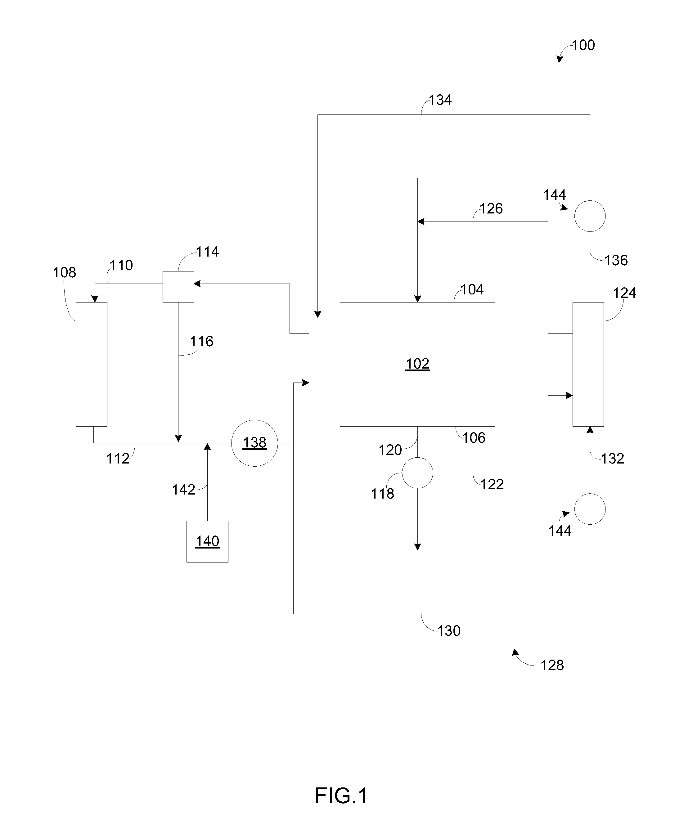
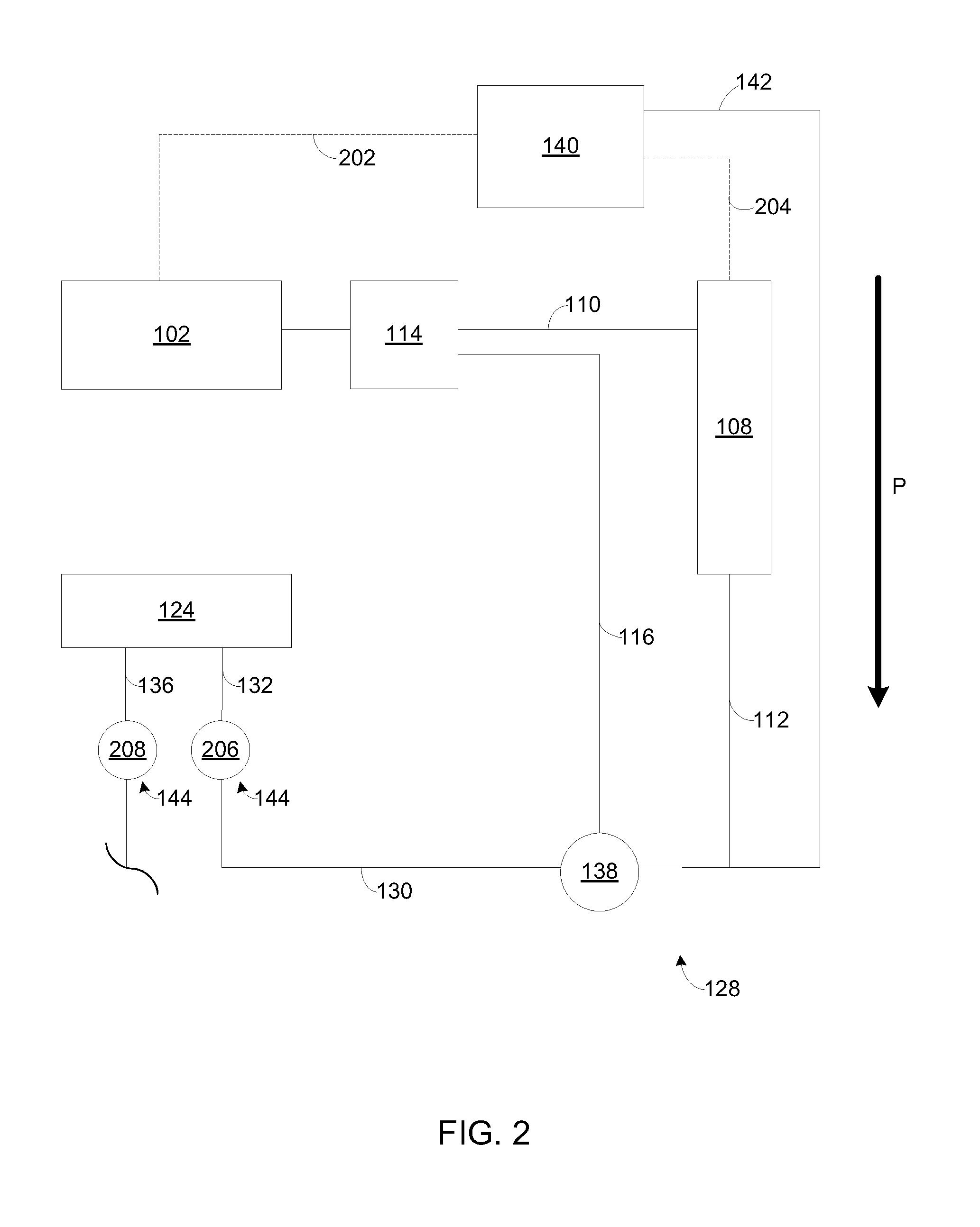
[0011]FIG. 1 illustrates an exemplary exhaust gas re-circulation (EGR) system 100 according to one embodiment of the present disclosure. The EGR system 100 may include a power source 102. In one embodiment, the power source 102 may include for example, a diesel engine, a gasoline engine, a gaseous fuel powered engine such as a natural gas engine, a combination of known sources of power or any other type of power source apparent to one of skill in the art. As shown, the power source 102 may include an intake manifold 104 and an exhaust manifold 106. The intake manifold 104 is configured to receive intake air, which may or may not be mixed with fuel. Products of combustion may be exhausted from the power source 102 via the exhaust manifold 106.

[0012]The power source 102 may be coupled a cooling system including passages within the power source 102 through which a coolant may flow. A heat exchanger or a radiator 108 may be fluidly connected to the power source 102, in order to dissipat...


PUM

PropertyMeasurementUnit
Forceaaaaaaaaaa
Pressureaaaaaaaaaa
Flow rateaaaaaaaaaa

Abstract

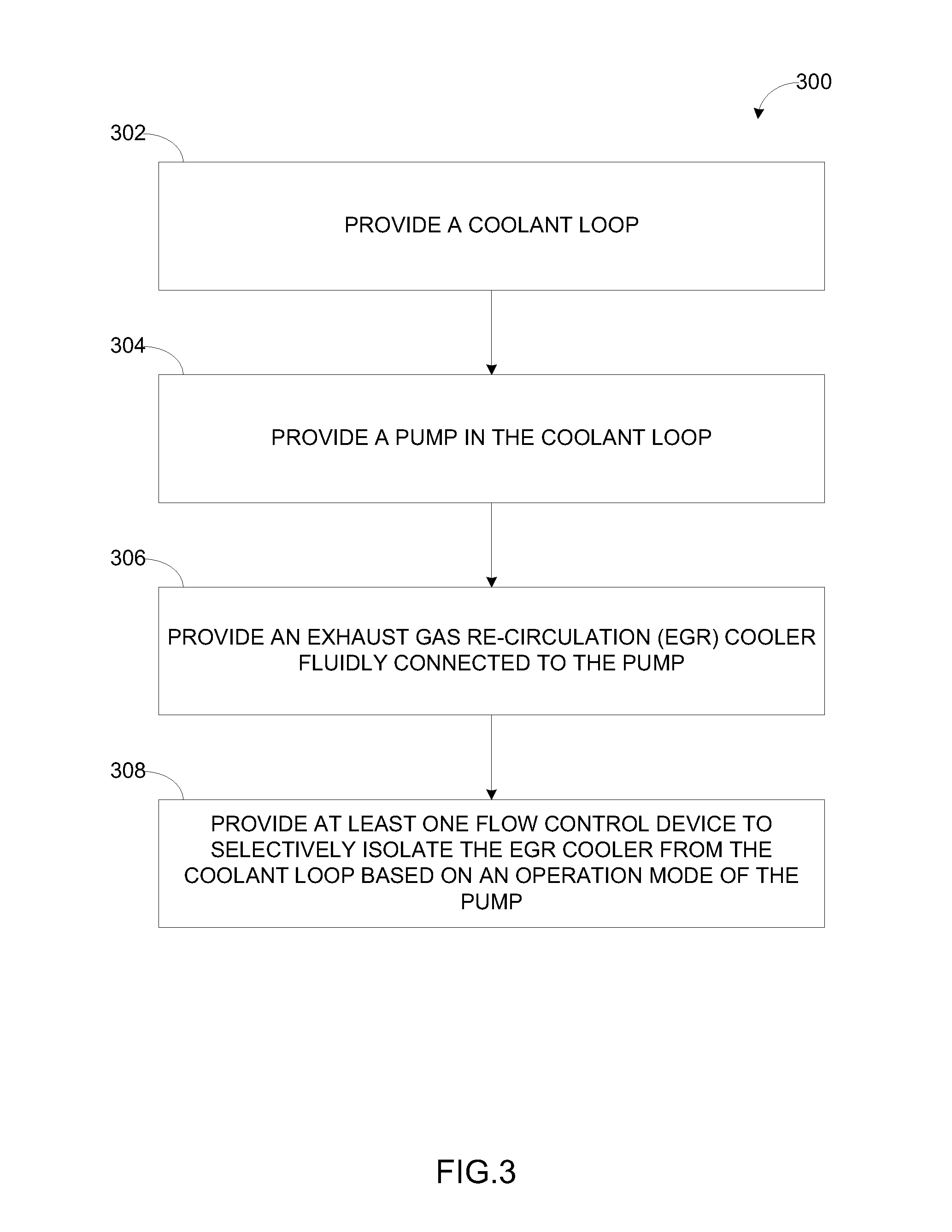
A system is provided. The system includes a coolant loop, a pump, and an exhaust gas re-circulation (EGR) cooler. The pump is disposed in the coolant loop. The EGR cooler is fluidly connected to the pump. Further, the system includes at least one flow control device to selectively isolate the EGR cooler from the coolant loop based on an operation mode of the pump.

Description

TECHNICAL FIELD[0001]The present disclosure relates to engine systems and more particularly to an exhaust gas re-circulation system of the engine system.BACKGROUND[0002]An exhaust gas re-circulation (EGR) cooler may be provided in an engine system to cool heated exhaust gases being re-circulated into an intake manifold. Occasionally, the EGR cooler may experience failure. In certain circumstances EGR failure may cause a coolant flowing through the EGR cooler to leak into an EGR exhaust loop. During engine shutdown, this leaked coolant may collect in the intake manifold and / or cylinders of the engine. The collected coolant may then cause hydro-lock when the engine is restarted.[0003]For example, U.S. Pat. No. 7,845,339 ('339 patent) relates to a cooling system for an engine. In one embodiment, the cooling system may include a heat exchanger, a pump coupled to the heat exchanger, an EGR cooler coupled to the pump, and a first valve coupled to the EGR cooler and the heat exchanger. Whe...

Claims


Application Information

Patent Timeline
IPC IPC(8): F02B47/08B21K3/00F02M25/07
CPCF02M26/28Y10T29/49231
Inventor DE LUCA, ANTHONY L.SCHURICHT, SCOTT R.
Owner CATERPILLAR INC
Learn More