Disk brake

a technology of disk brakes and brake pads, applied in the direction of axially engaging brakes, fluid actuated brakes, mechanical devices, etc., can solve problems such as damage to the brake body, and achieve the effect of improving the reliability of the disk brak

Active Publication Date: 2014-02-06
HITACHI ASTEMO LTD
View PDF9 Cites 27 Cited by
  • Summary
  • Abstract
  • Description
  • Claims
  • Application Information

AI Technical Summary

Benefits of technology

[0006]According to the disk. brake of the present invention,

Problems solved by technology

However, in the disk brake disclosed in International Publication WO2011/076299, the harness is disposed to extend to the

Method used


Image

  • Disk brake
  • Disk brake
  • Disk brake

Examples


Embodiment Construction

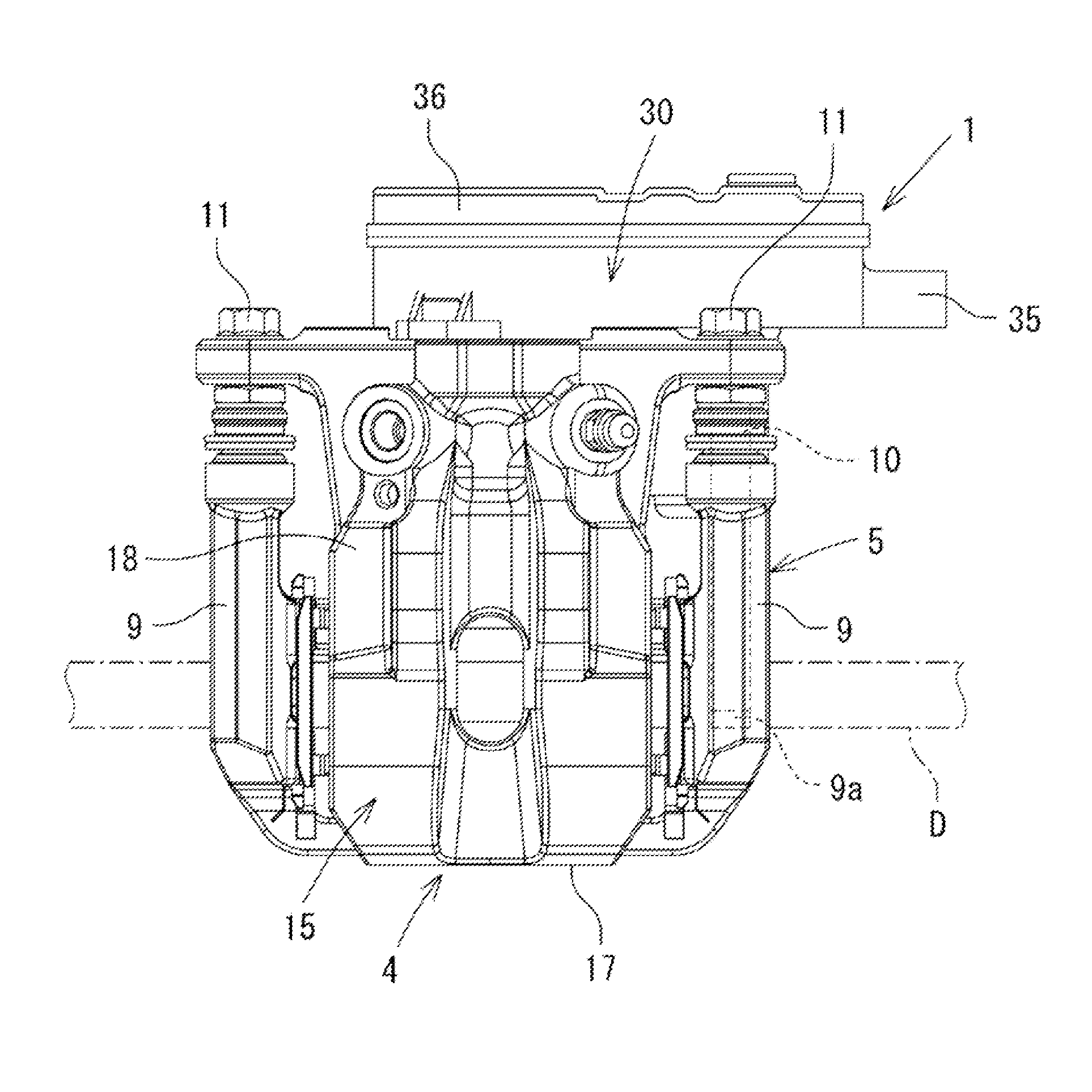
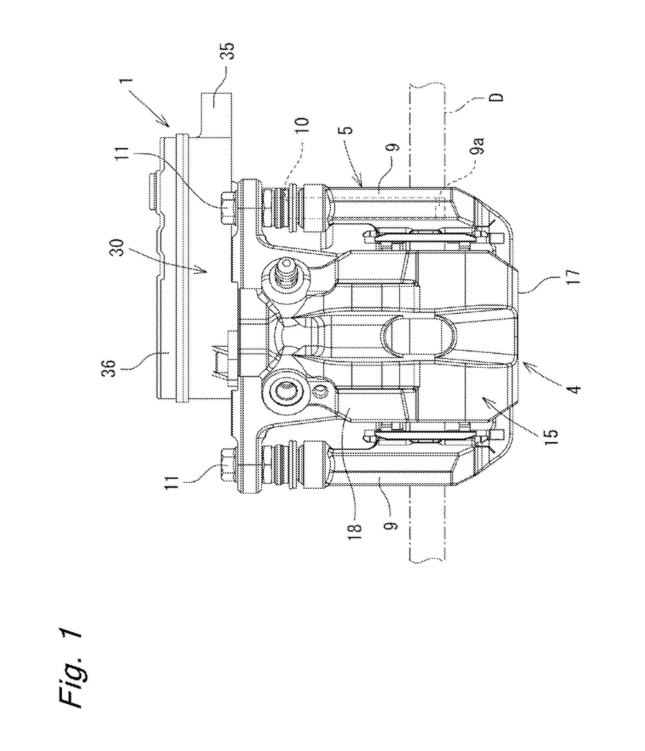
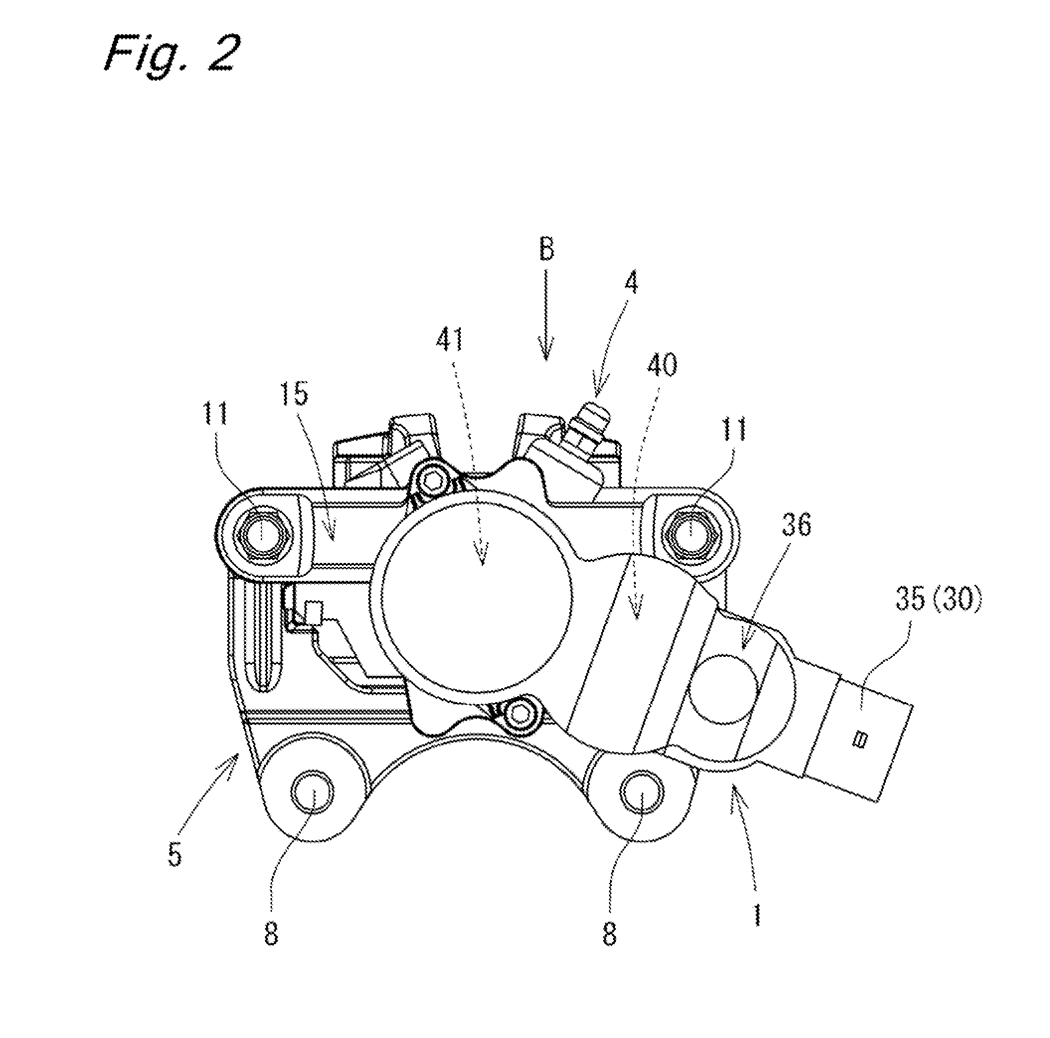
[0023]Hereinafter, embodiments of the present invention will be described in detail with reference to FIGS. 1 to 16. As illustrated in FIGS. 1 to 3, a disk brake 1 according to the embodiments of the present invention includes a pair of brake pads 2 and 3 disposed at both axial sides opposite of a disk rotor D attached to a rotational portion of a vehicle, a caliper 4, and a bracket 5 supporting them. The disk brake 1 is configured as a caliper floating type disk brake, and the above-described pair of brake pads 2 and 3 and caliper 4 are supported by the bracket 5 fixed to a non-rotatable portion (not illustrated) such as a knuckle of the vehicle so as to be movable in the axial direction of the disk rotor D. In the following description, the term “inner brake pad 2” will be used to refer to the brake pad disposed at the inner site of the vehicle relative to the disk rotor D among the pair of brake pads 2 and 3, and the term “outer brake pad 3” will be used to refer to the brake pad...


PUM


Abstract

An object of the present invention is to provide a highly reliable disk brake. In a disk brake 1 according to the present invention, a connector portion 35 is provided at a housing 30. The connector portion 35 includes supply terminals 131 for supplying power to a motor 32. The supply terminals 131 of the connector portion 35 and motor terminals 32C of the motor 32 are connected to each other via bus bars 130 made of metallic plate. Further, the bus bars 130 are held in a loosely fitted state on another-side surface 138B of a plate-like portion 138 of a support member 135 attached to the housing 30.

Description

BACKGROUND OF THE INVENTION[0001]The present invention relates to a disk brake for use in braking a vehicle.[0002]For example, International Publication WO2011 / 076299 discloses a disk brake configured to move a piston with use of a driving three of an electric motor. This disk brake uses a flexible harness for an electric connection between the electric motor and connector connected to an ECU configured to drive and control the electric motor.[0003]However, in the disk brake disclosed in International Publication WO2011 / 076299, the harness is disposed to extend to the outer circumferential side of a reduction gear, whereby the harness may be damaged due to contact with the reduction gear.SUMMARY OF INVENTION[0004]An object of the present invention is to provide a highly reliable disk brake.SOLUTION TO PROBLEM[0005]To achieve the above-descried an other objects, the present invention is a disk brake includes a caliper configured to press a pad against a disk by a piston slidably disp...

Claims


Application Information

Patent Timeline
IPC IPC(8): F16D55/226
CPCF16D55/226F16D65/18F16D65/567F16D2121/04F16D2121/24F16D2123/00F16D2125/36F16D2125/48F16D2125/50F16D65/095
Inventor FUSE, TAKAAKITSURUMI, SATORUWATANABE, JUNSAKASHITA, TAKAYASU
Owner HITACHI ASTEMO LTD
Why Eureka
Try Eureka