Link member having replaceable wear component

Active Publication Date: 2014-02-06
ASHWORTH BROS
View PDF8 Cites 2 Cited by
  • Summary
  • Abstract
  • Description
  • Claims
  • Application Information

AI Technical Summary

Benefits of technology

[0010]Thus, an advantage of embodiments of the present invention is that the wear component can be removed and a new component can be installed to bring the conveyor belt to nearly new condition. This wi

Problems solved by technology

Further, there exists an unfulfilled need for such a wear component that

Method used


Image

  • Link member having replaceable wear component
  • Link member having replaceable wear component
  • Link member having replaceable wear component

Examples


Example

[0026]A link member having a replaceable wear component is described. In the following description, for purposes of explanation, numerous specific details are set forth in order to provide a thorough understanding of the exemplary embodiments. It is apparent to one skilled in the art, however, that the present invention can be practiced without these specific details or with an equivalent arrangement.

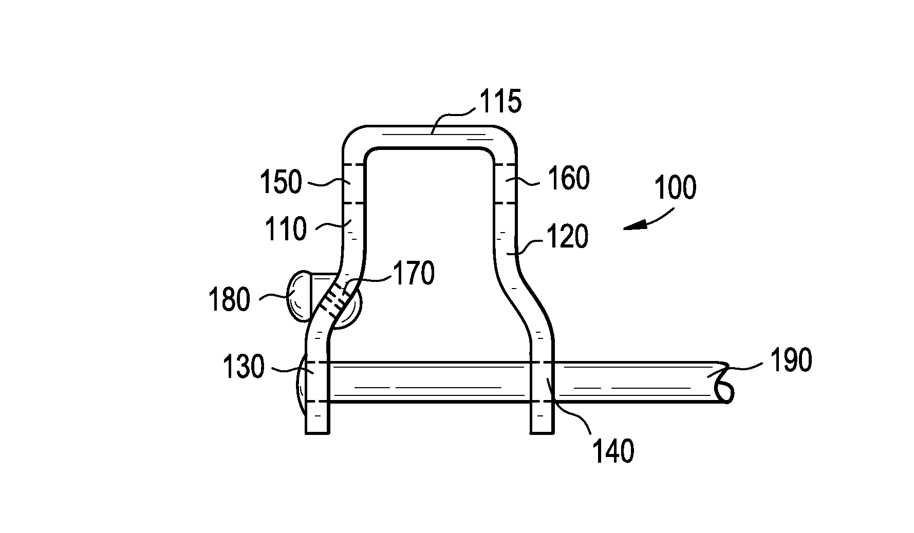
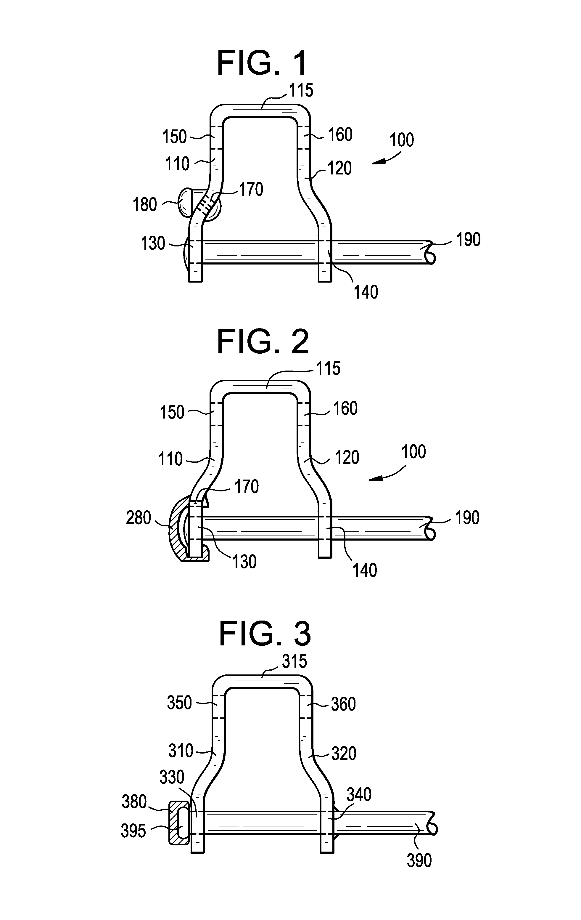
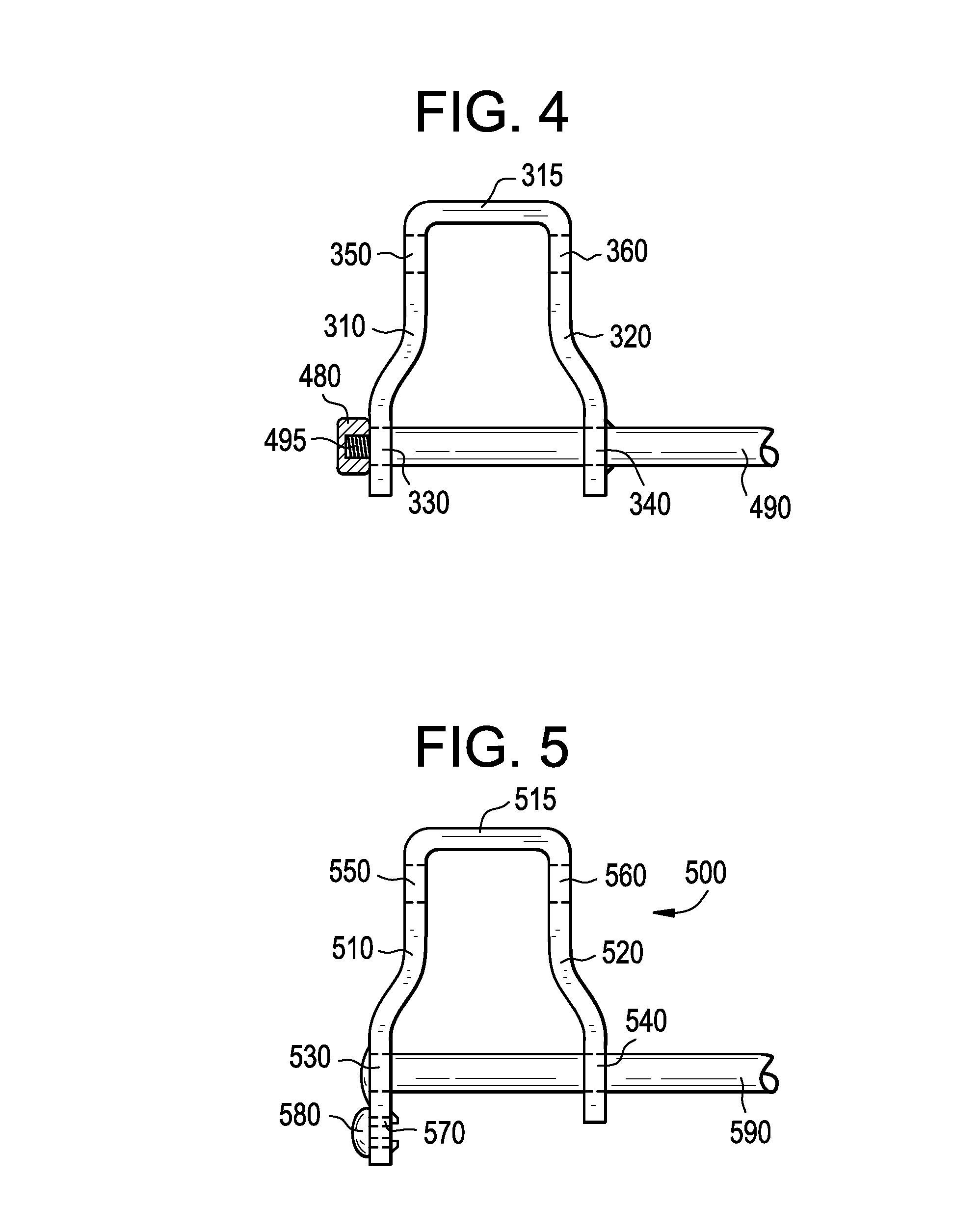
[0027]Referring now to the drawings, wherein like reference numerals designate identical or corresponding parts throughout the several views, FIG. 1 is a top view of a link member 100 having a wear component 180, in accordance with one implementation of the invention. Link member 100 has a first leg portion 110, a connecting portion 115 and a second leg portion 120. Connecting portion 115 connects first leg portion 110 and second leg portion 120 at a distal end of link member 100. First leg portion 110 and second leg portion 120 extend proximally from connecting portion 115. Although sh...


PUM


Abstract

A link member having a replaceable wear component and a conveyor belt comprising a link member having a replaceable wear component are described. One aspect of the present invention provides a sacrificial or replaceable wear component that is attached to a conveyor belt. The conveyor belt can be any type of conveyor belt, such as a grid-type or flat-wire conveyor belt. The wear component is attached by mechanical or other means to allow its removal after a certain wear limit has been achieved. A new component can be installed to bring the conveyor belt to nearly new condition. This will extend belt life because only the wear component needs to be replaced, rather than the entire belt.

Description

BACKGROUND OF THE INVENTION[0001]1. Field of the Invention[0002]The present invention relates to conveyor belts, and in particular, to a link member having a replaceable wear component.[0003]2. Description of Related Art[0004]Conveyor belt systems are commonly used in various industrial fields for material handling and processing purposes. For instance, conveyor systems are used within food processing systems in which food items are placed on the support surface of a conveyor belt and processed, while being conveyed from one location to another. Various types of conveyor belts exist, including modular conveyor belts, which are especially popular in food processing systems. Moreover, conveyor systems are often used in a helical accumulator such as that disclose in U.S. Pat. No. 5,070,999 to Layne et al. which allows storage of a large number of items in the conveyor system.[0005]Conveyor belts used in spiral ovens are driven by a spiral cage made with evenly spaced vertical bars or a...

Claims


Application Information

Patent Timeline
IPC IPC(8): B65G17/06
CPCB65G17/064B65G17/086B65G2201/0202B65G2207/48B65G17/083B65G17/40B65G17/08
Inventor LACKNER, JOSEPH M.STEINHOFF, PAULLASECKI, JONATHAN R.
Owner ASHWORTH BROS
Why Eureka
Try Eureka