Measuring device for measuring a measurement object and related method

Active Publication Date: 2014-02-13
CARL ZEISS IND MESSTECHN GMBH
View PDF5 Cites 4 Cited by
  • Summary
  • Abstract
  • Description
  • Claims
  • Application Information

AI Technical Summary

Benefits of technology

The invention described in this patent makes it easier to evaluate the size of objects using a microscope. It does this by ensuring that the object is in focus and at the same distance from the microscope, regardless of its position in the device. This makes it easier to get accurate measurements and doesn't require adjusting the size of the image being used. In addition, the invention allows for the use of parallel and coaxial illumination and observation beam paths, which makes it possible to examine narrow or recessed environments.

Problems solved by technology

However, the speed of such systems that effect tactile measurement is limited.
The size of the probe element additionally limits the measurable radii of the surface, i.e. small depressions generally cannot be detected.
Furthermore, under certain circumstances, very hard probe elements can cause damage to very sensitive surfaces.
Furthermore, in the case of highly scattering surfaces, problems can occur on account of ambiguities in the evaluation.
Consequently, all interferometric methods also require a reference beam path, which, however, always has a high sensitivity to disturbance in the measurement set-up.
However, in particular spatially greatly restricted applications which allow only limited viewing angles with respect to the surface to be measured, for example the measurement of bores or channels, do not allow large angles between the illumination direction and viewing direction, and so the precision of the methods that effect areal measurement thus also decreases.

Method used


Image

  • Measuring device for measuring a measurement object and related method
  • Measuring device for measuring a measurement object and related method
  • Measuring device for measuring a measurement object and related method

Examples


Embodiment Construction

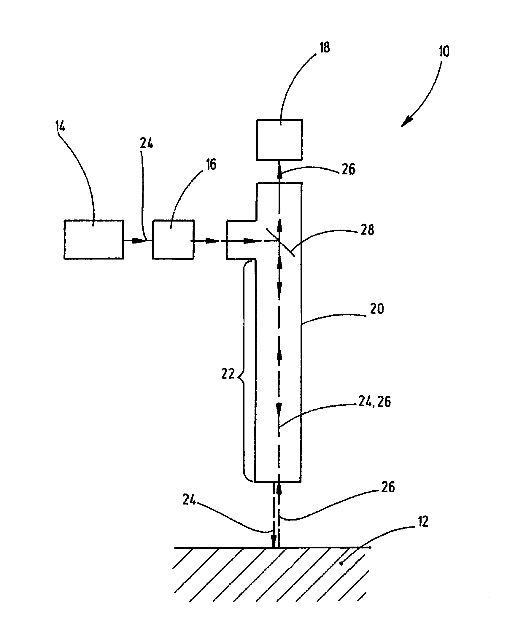
[0066]FIG. 1 shows a schematic illustration of a measuring device 10. The measuring device 10 serves for measuring a measurement object 12.

[0067]For this purpose, the measuring device 10 comprises an illumination device 14 and a pattern generating device 16. By means of the illumination device 14 and the pattern generating device 16, an illumination pattern is radiated onto the measurement object 12, wherein the light reflected and / or scattered by the measurement object 12 is detected by means of an optical sensor arrangement 18.

[0068]The measuring device 10 can comprise a housing 20 having a housing section 22 extending in elongate fashion, which housing section can be pushed for example into a region that otherwise is difficult to access in spatial terms, for example a bore. In principle, however, the spatial-physical configuration of the measuring device 10 is arbitrary.

[0069]A beam path 24 runs from the illumination device 14 to the measurement object 12. The light which is refl...


PUM


Abstract

A measuring device and corresponding method for measuring a measurement object, comprising an illumination device for illuminating the measurement object with an illumination pattern, a pattern generation device with at least one pattern generating element for bringing about a positionally variant intensity distribution of the illumination pattern, and an optical sensor arrangement for detecting the illumination pattern reflected and / or scattered by the measurement object. The measuring device has an optics which is telecentric at least on the measurement object side and is arranged in a beam path from the illumination device to the measurement object. The optical sensor arrangement detects the illumination pattern through at least one part of the telecentric optics. The pattern generating device is designed in such a way that the illumination pattern has a positionally and / or spectrally variant vertex focal length distribution on the measurement object side.

Description

CROSS-REFERENCE TO RELATED APPLICATIONS[0001]This application is a continuation of International PCT application No. PCT / EP2012 / 074381, filed Dec. 4, 2012, and a continuation-in-part of International PCT application No. PCT / EP2012 / 065477, filed Aug. 7, 2012. This application also claims priority of U.S. provisional application No. 61 / 733,110, filed Dec. 4, 2012 and U.S. provisional application No. 61 / 680,454, filed on Aug. 7, 2012. The entire contents of these priority applications are incorporated herein by reference.BACKGROUND OF THE INVENTION[0002]The present invention relates to a measuring device for measuring a measurement object, comprising an illumination device for illuminating the measurement object with an illumination pattern, a pattern generation device with at least one pattern generating element for bringing about a positionally variant intensity distribution of the illumination pattern, and an optical sensor arrangement for detecting the illumination pattern reflecte...

Claims


Application Information

Patent Timeline
IPC IPC(8): G01N21/55G01N21/25
CPCG01N21/25G01N21/55G01N21/21
InventorWESTPHAL, PETERENGEL, THOMAS
OwnerCARL ZEISS IND MESSTECHN GMBH