Reverse Notification Tree For Data Networks

a data network and reverse notification technology, applied in the field of data networks, can solve the problems of inability to recover from a network failure in a timely manner, the amount of time required to recover from a link or switch the time required to recover from a network failure can take several seconds to several minutes, so as to minimize the loss of data, reduce the recovery time of network faults, and minimize the effect of data loss

Inactive Publication Date: 2014-02-13
TELLABS OPERATIONS
View PDF3 Cites 23 Cited by
  • Summary
  • Abstract
  • Description
  • Claims
  • Application Information

AI Technical Summary

Benefits of technology

[0010]In an MPLS data network comprised of various transmission media linking various types of switching systems, network fault recovery time is reduced by using a reverse-directed status message that is generated by a data switch that is down-stream from a switching system from which data is received. The reverse-directed or upstream status message is sent over a pre-determined pathway (i.e. through pre-determined switches and / or over pre-determined data links) which originates from a destination switch or node in an MPLS network to upstream switching systems. This so-called reverse notification tree carries a message or messages that are used to indicate the functionality (or non-functionality) of the downstream switch, switches or links of the MPLS network. As long as an upstream MPLS switching system continues to receive the reverse-directed status message from a downstream switch via the reverse notification tree, the switching systems that receive such a message consider the downstream switch and pathways to be intact. Accordingly, data packets continue to be sent downstream for subsequent routing and / or processing. If the reverse-directed status message is lost or discontinued, either because of a switch failure or a link failure, the upstream switching system considers the downstream switch or link to have failed and thereafter begins executing a procedure by which data is rerouted over an alternate data path through the network. In the preferred embodiment, the alternate data path over which downstream information is sent is a pre-established protection path and is known to a protection switch in advance, thereby minimizing data loss attributable to the time it might take to calculate a dynamic alternate protection path.
[0011]Switches in the network and their interconnections can be modeled using a directed acyclical graph by which a downstream switch knows the identity of the upstream switch to which the failure notice should be sent. In the preferred embodiment, at least one upstream switch routing the MPLS data re-directs data onto a protection path through the network between the same two endpoints by using the reverse notification tree. By way of the reverse notification tree, data loss caused by either a link or switch failure can be minimized by the prompt rerouting of the data through an alternate or recovery data path through the network.

Problems solved by technology

A problem with any data network, including an MPLS network, is the amount of time required to recover from either a link failure or a switch failure.
Empirical data shows that the time required to recover from a network failure can take several seconds to several minutes, an unacceptably long time.

Method used


Image

  • Reverse Notification Tree For Data Networks
  • Reverse Notification Tree For Data Networks
  • Reverse Notification Tree For Data Networks

Examples


Embodiment Construction

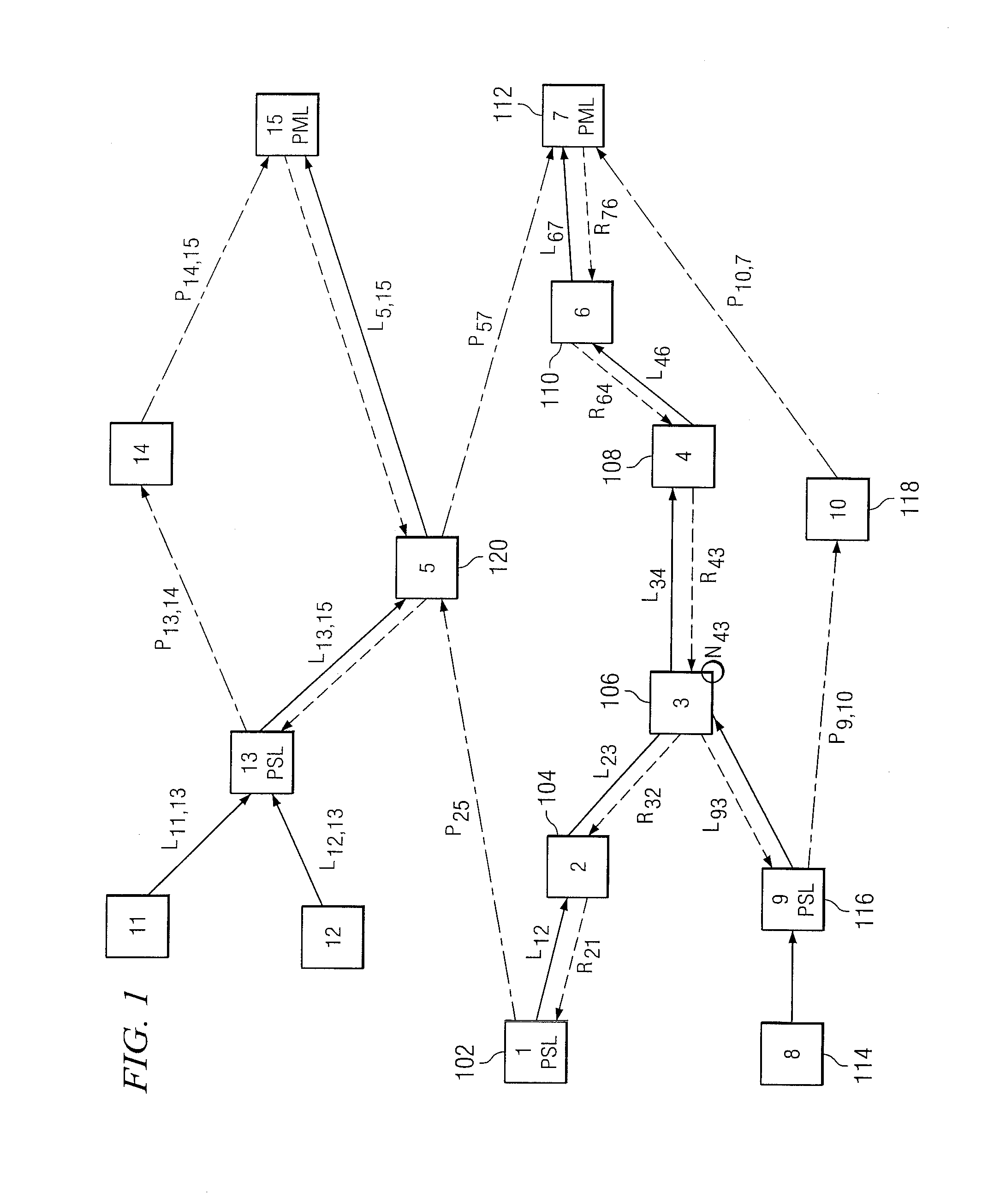
[0014]FIG. 1 shows a simplified block diagram of a packetized-data switching network 100. Each of the squares shown in FIG. 1 including boxes represented by reference numerals 102, 104, 106, 108, 110, 112, 114, 116, 118 and 120 represent one or more types of asynchronous switching systems that asynchronously receive data in e.g., packets, cells or frames from an “upstream” switch and route, direct, couple or otherwise send the data onward to another “downstream” switch logically closer to the ultimate destination for the data. By way of example, these switching systems might be internet protocol (IP) routers, asynchronous transfer mode (ATM) switches, frame relays switches or other types of packetized-data switching systems implemented to receive packetized data over a transmission line and reroute the data onto one or more output ports to which are connected transmission media coupled to other switching systems.

[0015]In FIG. 1, switching system number 1, (identified by reference nu...


PUM


Abstract

Recovery time upon the failure of a link or switching system in an asynchronous data network can be minimized if downstream data switches provide upstream messages indicating to an upstream switching system that the downstream traffic arrived intact and was properly handled. Upon this loss or failure of the upstream status message to an upstream switching system, an upstream switching system can reroute data traffic around a failed link or failed switch with a minimal amount of lost data. The upstream status message is conveyed from a downstream switching system to an upstream switching system via a reverse notification tree data pathway.

Description

RELATED APPLICATIONS[0001]This application is a continuation application of U.S. application Ser. No. 12 / 968,985, filed Dec. 15, 2010, which is a continuation application of U.S. application Ser. No. 11 / 838,328, filed Aug. 14, 2007, which is a continuation application of U.S. application Ser. No. 09 / 693,276, filed Oct. 20, 2000, which claimed priority to U.S. Provisional Application No. 60 / 160,840, filed Oct. 21, 1999; U.S. Provisional Application No. 60 / 161,277, filed Oct. 25, 1999; and U.S. Provisional Application No. 60 / 187,798, filed Mar. 8, 2000. These prior applications, including the entire written description, claims, and drawing figures, are hereby incorporated into the present application by reference.TECHNICAL FIELD[0002]This invention relates to data networks. In particular this invention relates to a method and apparatus for providing a pathway through a multi-protocol label-switching (MPLS) network over which messages, which act to trigger the re-routing of data onto a...

Claims


Application Information

Patent Timeline
Patent Type & Authority Applications(United States)
IPC IPC(8): H04L12/703H04L12/723H04L45/28H04L45/50
CPCH04L45/50H04L45/28H04J3/14H04L43/0817H04L45/22H04L45/48H04L49/552H04L2012/5627H04L45/00
Inventor OWENS, KENNETH R.MAKAM, SRINIVAS V.HUANG, CHANGCHENGSHARMA, VISHAL
Owner TELLABS OPERATIONS
Why Eureka
Try Eureka