Fiber optic systems for MRI suites and related devices and methods

Active Publication Date: 2014-02-13
CLEARPOINT NEURO INC
View PDF31 Cites 24 Cited by
  • Summary
  • Abstract
  • Description
  • Claims
  • Application Information

AI Technical Summary

Benefits of technology

[0008]The systems can be configured to allow for easy installation without r

Problems solved by technology

Holes or openings made in this shielding can compromise the shielding effectiveness.
Shielding effectiveness of an MRI suite can be compromi

Method used


Image

  • Fiber optic systems for MRI suites and related devices and methods
  • Fiber optic systems for MRI suites and related devices and methods
  • Fiber optic systems for MRI suites and related devices and methods

Examples


Embodiment Construction

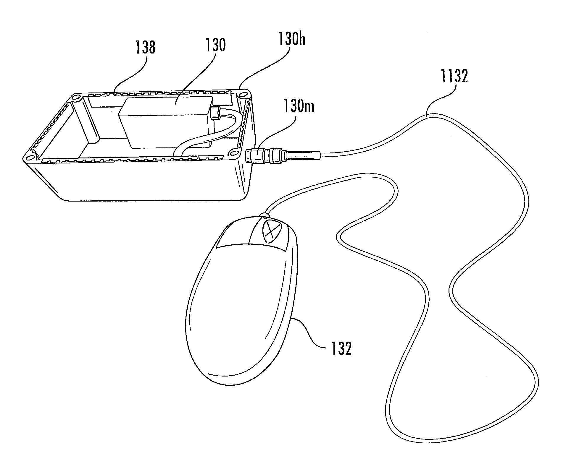
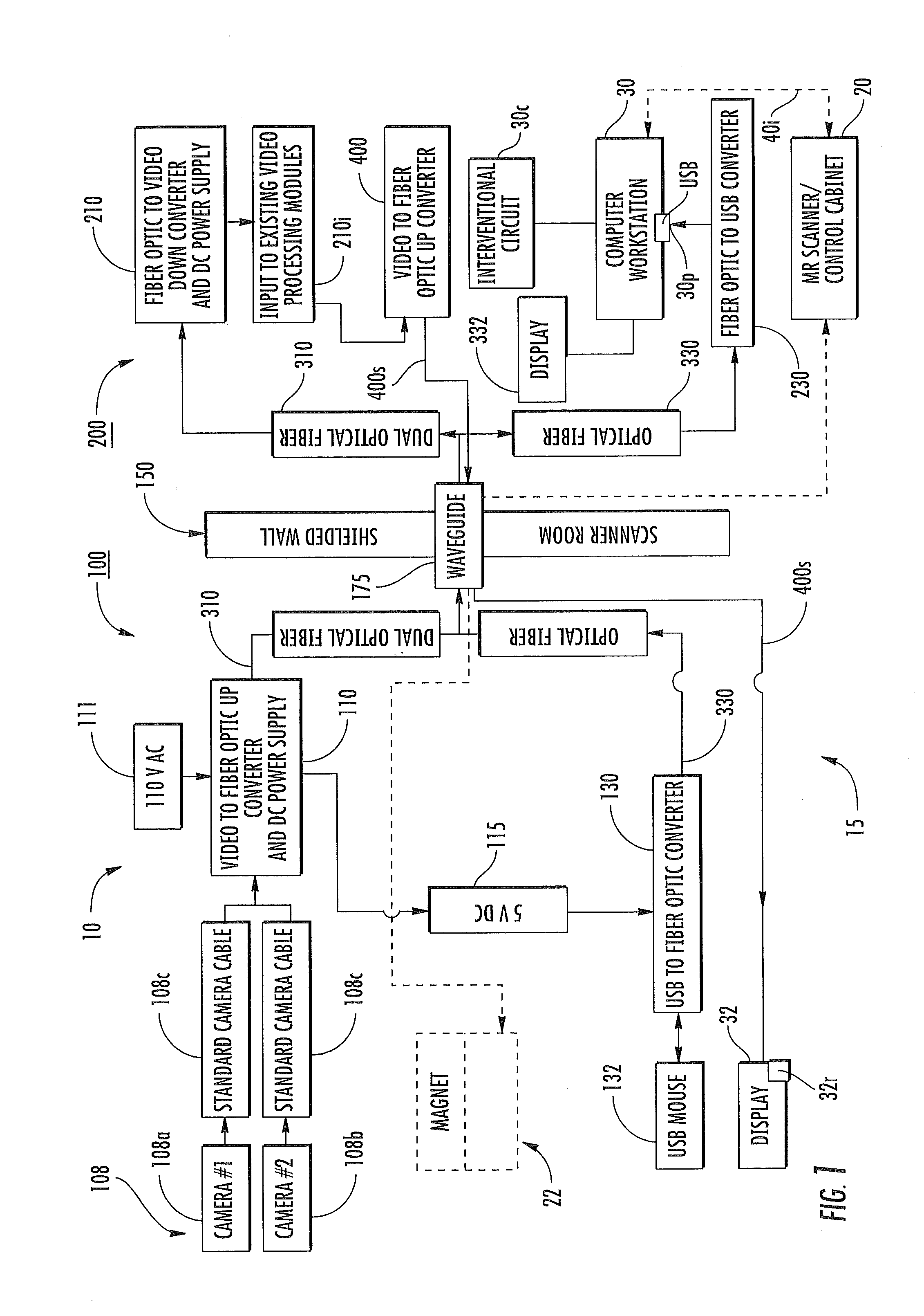
[0007]Embodiments of the invention provide a computer interface mouse with fiber optic interfaces that use fiber optic cables that extend through the wave guide (or through connectors in the penetration panel) and connect devices on the scanner room side to devices on the control room side.

[0008]The systems can be configured to allow for easy installation without requiring any physical modification to the RF shielding or penetration panel.

[0009]Some embodiments are directed to surgical systems for an MRI suite. The systems include an MRI compatible mouse residing in an MR Scanner room of the MRI suite, a fiber optic mouse interface in the MR Scanner room in communication with the mouse, and a fiber optic cable attached to the fiber optic mouse interface configured to connect a computer outside the MR scanner room. A user is able to move the mouse in the MR Scanner room to move a cursor on the monitor and / or select actions or functions in drop down menus presented by the computer to ...


PUM


Abstract

Fiber optic systems with an MR compatible mouse in an MR scanner room that connects to a fiber optic computer mouse interface that is attached to a fiber optic cable that connects to a USB port of a computer in the MR control room to allow the mouse in the MR scanner room to move a cursor on a monitor in communication with the computer in the control room of an MRI suite during an MRI guided surgical procedure. The fiber optic cable(s) can be routed though a conventional RF wall waveguide and avoids the need for additional holes in the penetration panel for connectors. The fiber optic systems can also include up converters and down converters for providing fiber optic video signals from cameras in the MR scanner room to display video signal on the monitor.

Description

RELATED APPLICATIONS [0001]This application claims the benefit of and priority to U.S. Provisional Patent Application Ser. No. 61 / 681,216 filed Aug. 9, 2012, the contents of which are hereby incorporated by reference as if recited in full herein.FIELD OF THE INVENTION[0002]The present invention relates generally to communication interfaces that connect control user interfaces (UI) in an MRI Scanner room to devices in a control room with an RF shielded wall therebetween.BACKGROUND OF THE INVENTION[0003]MRI suites have a control room with MRI Scanner operating components such as an RF amplifier and control cabinet (typically called the control room) and a separate room or chamber holding a high field magnet in which a patient is placed for an MRI procedure (typically called the Scanner room). MRI suites are enclosed in a Faraday shield (e.g., RF shielding) in order to electrically isolate sensitive MRI radio receivers and prevent them from picking up RF signals other than those emitte...

Claims


Application Information

Patent Timeline
IPC IPC(8): A61B5/00A61B5/055
CPCA61B5/7475A61B5/0046A61B5/055
Inventor VIJ, KAMALPIFERI, PETERKAIL, RICHARD JAMES
Owner CLEARPOINT NEURO INC
Why Eureka
Try Eureka